
Παράδειγμα σχεδιασμού πλάκας βάσης χρησιμοποιώντας AISC 360-22 και ACI 318-19
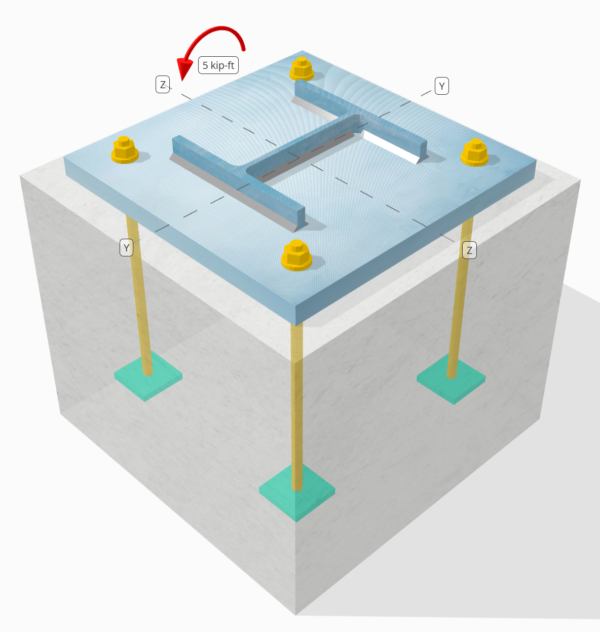
Προβληματική δήλωση
Προσδιορίστε εάν η σχεδιασμένη σύνδεση στήλης-πλάκας βάσης είναι επαρκής για α 5 kip-ft strong-axis moment.
Δεδομένα
Στήλη:
Ενότητα στήλης: W8x31
Επιφάνεια στήλης: 9.130 σε2
Υλικό στήλης: A992
Πλάκα βάσης:
Διαστάσεις πλάκας βάσης: 15 σε x 15 σε
Πάχος πλάκας βάσης: 1 σε
Υλικό πλάκας βάσης: A36
Σκυρόδεμα:
Διαστάσεις σκυροδέματος: 18 σε x 18 σε
Πάχος σκυροδέματος: 15 σε
Σκυρόδεμα: 3000 psi
Συγκολλήσεις:
Μέγεθος συγκόλλησης: 1/4 σε
Η ταξινόμηση μετάλλων πλήρωσης: μι70ΧΧ
Το φορτίο συμπίεσης μεταφέρθηκε μόνο μέσω συγκολλήσεων? ΟΧΙ
Μοντέλο στο δωρεάν εργαλείο SkyCiv
Μοντελοποιήστε το παραπάνω σχέδιο πλάκας βάσης χρησιμοποιώντας το δωρεάν διαδικτυακό μας εργαλείο σήμερα! Δεν απαιτείται εγγραφή.
Determine if Low Moment or Large Moment
The calculations for this base plate example, which is subjected to a strong-axis moment, will be based on Οδηγός σχεδίασης AISC 1, 3έκδοση. According to the design guide, base plates subjected to moment loads only are classified as the Large Moment Case. This is because no axial load is present to counteract the eccentric load acting on the connection.
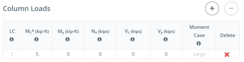
For other load combinations, such as strong-axis bending with axial compression or strong-axis bending with axial tension, determining if the case is Large Moment or Low Moment depends on the actual μέγεθος στήλης, base plate size, concrete size, and the given φορτία.
In the free version of SkyCiv, the moment case is displayed as you enter the load values. You can access the free tool here to determine the moment case yourself. Straight from the browser, δεν απαιτείται εγκατάσταση.
To learn more about Low Moment and Large Moment case, refer to this SkyCiv article: AISC DG1: Πλάκες βάσης με μεγάλη ροπή και χαμηλή ροπή
Υπολογισμοί βήμα προς βήμα
Ελεγχος #1: Weld capacity
We start the design by checking the weld capacity of the connection. We use the Blodgett equations from Σχεδιασμός Συγκολλημένων Κατασκευών από τον Omer W. Blodgett to determine the weld section modulus of the weld. We take the weld shape shown below as a simplification.
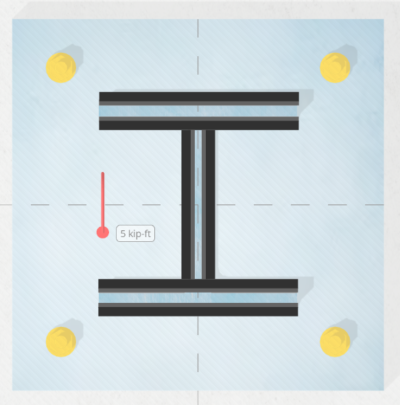
\(S_w = 2d_{col}b_f + \dfrac{(d_{col})^2}{3} = 2 \times 8 \text{ in} \times 8 \text{ in} + \dfrac{(8 \text{ in})^2}{3} = 149.33 \text{ in}^2\)
Επόμενο, we divide the applied bending moment by the weld section modulus to determine the weld stress per unit length. Note that in calculating the weld section modulus, we assume the critical weld stresses occur at the outermost fiber. For a weld in an I-shaped section, the critical locations are at the outer flanges. We get the weld stress as:
\(r_{uw} = \dfrac{M_z}{S_w} = \dfrac{5 \text{ kip·ft}}{149.33 \text{ in}^2} = 0.40179 \text{ kip/in}\)
Τότε, υπολογίζουμε το capacity of the weld. Για ένα 0.25 in weld size, the design weld throat is 0.177 σε, which is obtained by multiplying the weld size by \(\dfrac{\sqrt{2}}{2}\). Χρησιμοποιώντας AISC 360-22 Εξ. J2-4, the weld capacity per unit length is:
\(\phi r_n = \phi 0.6F_{exx}E_w k_{ds} = 0.75 \times 0.6 \times 70 \text{ ksi} \times 0.177 \text{ in} \times 1 = 5.5755 \text{ kip/in}\)
Από 0.40179 KPI < 5.5755 KPI , the column weld capacity is επαρκής.
This weld check investigates the weld stress at the tension flange. Since the geometry is symmetric and the only load is a moment acting at the center, we can assume the stress at the compression flange is the same as the stress at the tension flange. Επομένως, the welds at the compression flange also have enough capacity.
Σε αυτό το παράδειγμα σχεδίασης, ωστόσο, the design inputs specify that compression is not transferred through the welds, but through ρουλεμάν. Ετσι, in the next check, we evaluate the bearing capacity of the column.
Ελεγχος #2: Calculate column bearing capacity
After evaluating the weld capacity, we make sure the column has enough capacity to bear on the base plate. This is necessary because we assume the welds do not carry the compression load.
Πρώτα, καθορίζουμε το compressive stress at the critical section, which is still the flange. We then add any contribution from axial compression. Σε αυτήν την περίπτωση, there is none.
\(r_u = \dfrac{N_x}{A_{col}} + \dfrac{M_z 0.5d_{col}}{I_{zz,col}} = \dfrac{0 \text{ kip}}{9.13 \text{ in}^2} + \dfrac{5 \text{ kip·ft} \times 0.5 \times 8 \text{ in}}{110 \text{ in}^4} = 2.1818 \text{ ksi}\)
Τότε, χρησιμοποιούμε AISC 360-22 Section J7 Eq. J7-1 Για να προσδιορίσετε το φέρουσα ικανότητα:
\(\phi r_n = \phi 1.8F_{y\_col} = 0.75 \times 1.8 \times 50 \text{ ksi} = 67.5 \text{ ksi}\)
Από 2.1818 ksi < 67.5 ksi, Η χωρητικότητα φέτος στήλης είναι επαρκής.
Συνήθως, this check is not governing.
Ελεγχος #3: Υπολογίστε τη χωρητικότητα του σκυροδέματος
To calculate the concrete bearing capacity, we need two areas. See the figure below as a guide.
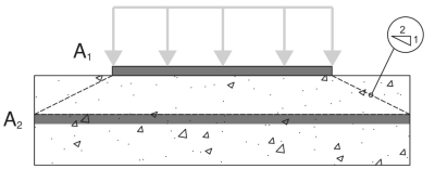
- A1 – Base plate loaded area
- A2 – Area of the concrete support with the same shape as A1
Α'1 είναι το loaded area of the base plate, while Α2 είναι το same loaded area projected at a 2H:1V slope into the concrete support. More details on these areas can be found in ACI 318-19 Ενότητα 22.8.3.2.
Σε αυτό base plate design with moment, the A1 area will be calculated using the full width of the base plate, \(B\) και το actual bearing length, \(Y\). The actual bearing length is measured from the edge of the base plate at the compression side towards the center of the plate.
\( A_1 = B \times Y \)
For most engineers, calculating A1 and A2 requires a lot of work, so they simply assume A1 = A2, που είναι συντηρητικό. Στο Λογισμικό SkyCiv Base Plate, επαναλήψεις are performed to determine the actual A1 values and to maximize the capacity of the base plate.
The table below shows the iteration steps from SkyCiv to determine the bearing length Y, και στη συνέχεια, to determine the actual A1 and A2 areas.

Πρώτα, an initial Y is assumed, and the A2 and A1 values are calculated based on the initial Y. These are then used to calculate the maximum bearing strength of the concrete, \(f_{p\_max}\), και το αντίστοιχο bearing force per unit length, \(q_{max}\). Once these are determined, the corresponding Y value is determined based on Εξ. 4-32 of AISC DG1 3rd Εκδοση. If the calculated Y does not match the initial Y, another iteration step is performed. A more detailed step-by-step calculation of the last iteration is shown in the next section.
Τώρα, taking the A2 and A1 values from the iteration, χρησιμοποιούμε Εξ. 4-2 of AISC Design Guide 1, 3έκδοση, to determine \(f_{p\_max}\), the design bearing strength for concrete crushing:
\(f_{p\_max} = \phi \left( \min \left( 0.85 \, (f_c’) \sqrt{\dfrac{A_2}{A_1}}, \, 1.7 \, (f_c’) \right) \right)\)
\(f_{p\_max} = 0.65 \times \left( \min \left( 0.85 \times (3 \text{ ksi}) \times \sqrt{39.941}, \, 1.7 \times (3 \text{ ksi}) \right) \right) = 3.315 \text{ ksi}\)
Επιπροσθέτως, since this design is a Large Moment Case, the base plate has both a compression side and a tension side. Σε αυτή την κατάσταση, we should allow the concrete bearing to be at its full capacity and minimize the Y value. Έτσι, any remaining tensile force, based on equilibrium of forces, will be taken by the anchors at the tension side.
Given this, we set \(f_{p\_actual}\) ίσο με \(f_{p\_max}\).
\(f_{p\_actual} = f_{p\_max} = 3.315 \text{ ksi}\)
Από 3.315 ksi ≤ 3.315 ksi, Η χωρητικότητα του σκυροδέματος είναι επαρκής.
Ελεγχος #4: Calculate base plate yielding capacity at the bearing interface
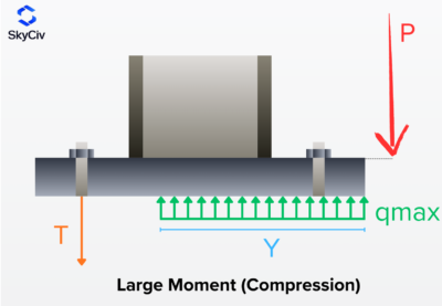
The next step is to determine if the base plate has enough capacity for the given load. As the moment load pushes the base plate against the concrete, the base plate has a tendency to yield due to flexure. We call this check the base plate yielding check on the bearing interface. There is also a separate yielding due to the tension load, and it will be covered in the next design check.
To check the base plate yielding, we need to determine the \(q_{max}\), which is the compression force per unit length. AISC DG1 3rd Ed. Εξ. 4-37 gives \(q_{max}\)όπως και:
\(q_{max} = f_{p\_max}B_{bp} = 3.315 \text{ ksi} \times 15 \text{ in} = 49.725 \text{ kip/in}\)
Τότε, we will calculate the Y-dimension. Although the Y-dimension is already calculated in the prior check, this section will show how we use the equations from AISC DG1. For this Large Moment Case, χρησιμοποιούμε Εξ. 4-32 of AISC DG1, 3έκδοση.
For the plus case:
\(Y_{case1} = \left( f + \dfrac{L_{bp}}{2} \right) + \sqrt{\left( \left( f + \dfrac{L_{bp}}{2} \right)^2 \right) – \dfrac{2M_z}{q_{max}}}\)
\(Y_{case1} = \left( 5.5315 \text{ in} + \dfrac{15 \text{ in}}{2} \right) + \sqrt{\left( \left( 5.5315 \text{ in} + \dfrac{15 \text{ in}}{2} \right)^2 \right) – \dfrac{2 \times 5 \text{ kip·ft}}{49.725 \text{ kip/in}}}\)
\(Y_{case1} = 25.97 \text{ in}\)
For the minus case:
\(Y_{case2} = \left( f + \dfrac{L_{bp}}{2} \right) – \sqrt{\left( \left( f + \dfrac{L_{bp}}{2} \right)^2 \right) – \dfrac{2M_z}{q_{max}}}\)
\(Y_{case2} = \left( 5.5315 \text{ in} + \dfrac{15 \text{ in}}{2} \right) – \sqrt{\left( \left( 5.5315 \text{ in} + \dfrac{15 \text{ in}}{2} \right)^2 \right) – \dfrac{2 \times 5 \text{ kip·ft}}{49.725 \text{ kip/in}}}\)
\(Y_{case2} = 0.092925 \text{ in}\)
Note that this equation has + και – σύμβολα, so we get two values. Από εδώ, we need to determine which value makes more sense. Από 25.97 σε is greater than the base plate length, 15 σε, we will not consider this value. Έτσι, θα το χρησιμοποιησουμε 0.092925 σε as the μήκος ρουλεμάν.
\(Y = Y_{case2} = 0.092925 \text{ in}\)
Επόμενο, we calculate the cantilever lengths. Αυτά είναι τα m and n dimensions from the figure below. Αυτό βασίζεται AISC DG1 3rd Edition Section 4.3.1.
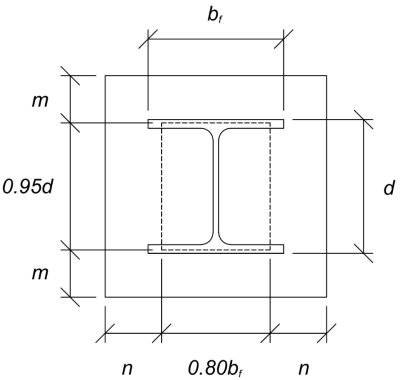
The calculated m and n cantilever values are:
\(m = \dfrac{L_{bp} – 0.95d_{col}}{2} = \dfrac{15 \text{ in} – 0.95 \times 8 \text{ in}}{2} = 3.7 \text{ in}\)
\(n = \dfrac{B_{bp} – 0.8b_f}{2} = \dfrac{15 \text{ in} – 0.8 \times 8 \text{ in}}{2} = 4.3 \text{ in}\)
Τότε, εμείς θα compare the calculated Y value to the larger of m and n. Since Y is less than the larger cantilever length, θα το χρησιμοποιησουμε AISC DG1 3rd Ed. Εξ. 4-52ένα. This gives the required base plate thickness to be:
\(t_{p(req)} = \sqrt{\dfrac{4f_{p\_actual}Y \left( n – \dfrac{Y}{2} \right)}{\phi F_{y\_bp}}}\)
\(t_{p(req)} = \sqrt{\dfrac{4 \times 3.315 \text{ ksi} \times 0.092925 \text{ in} \times \left( 4.3 \text{ in} – \dfrac{0.092925 \text{ in}}{2} \right)}{0.9 \times 36 \text{ ksi}}} = 0.4022 \text{ in}\)
Τελικά, let’s compare it to the actual base plate thickness.
\(t_{p(actual)} = t_{bp} = 1 \text{ in}\)
Από 0.4022 σε < 1 σε, the yielding capacity of the base plate is επαρκής.
Ελεγχος #5: Calculate base plate yielding capacity at the tension interface
The required tensile force on the anchors at the tension side is equal to the resulting compression force on the compression side. This is because the base plate is only loaded with moment loads, and so the resulting couple forces are equal in magnitude.
To calculate the required strength of anchors, χρησιμοποιούμε AISC DG1 3rd Ed. Εξ. 4-31.
\(T_u = q_{max}Y = 49.725 \text{ kip/in} \times 0.092925 \text{ in} = 4.6207 \text{ kip}\)
Τότε, υπολογίζουμε το eccentricity of this tensile force from the column support. This is taken from the center of the anchor rod to the center of the column flange. Χρησιμοποιούμε Εξ. 4-61 of the design guide to determine the eccentricity. In the equation, f is the distance of the anchor rod from the column centerline.
\(x = \left( f – \dfrac{d_{col}}{2} \right) + \dfrac{t_f}{2} = \left( 5.5315 \text{ in} – \dfrac{8 \text{ in}}{2} \right) + \dfrac{0.435 \text{ in}}{2} = 1.749 \text{ in}\)
Note that in this analysis, we take the whole base plate width as the section to resist the flexure, as we closely follow the AISC DG1 3rd Ed. guidelines. Other conservative bending widths could also be used.
Τελικά, we determine the required base plate thickness χρησιμοποιώντας Εξ. 4-62ένα.
\(t_{p(req)} = \sqrt{\dfrac{4T_u x}{B_{bp}\phi F_{y\_bp}}} = \sqrt{\dfrac{4 \times 4.6207 \text{ kip} \times 1.749 \text{ in}}{15 \text{ in} \times 0.9 \times 36 \text{ ksi}}} = 0.25791 \text{ in}\)
Από 0.25791 σε < 1 σε, ο yielding capacity of the base plate is επαρκής.
Ελεγχος #6: Έλεγχοι άγκυρας
The rest of the anchor design checks are not shown in this example. Please refer to other SkyCiv Base Plate Design Examples that covers capacity of αγκυροβόλιο.
Περίληψη σχεδίου
Το λογισμικό σχεδιασμού πλάκας βάσης SkyCIV μπορεί να δημιουργήσει αυτόματα μια αναφορά υπολογισμού βήμα προς βήμα για αυτό το παράδειγμα σχεδιασμού. Παρέχει επίσης μια περίληψη των επιταγών που εκτελούνται και των προκύπτουσων αναλογιών τους, καθιστώντας τις πληροφορίες κατανοητές με μια ματιά. Παρακάτω είναι ένας πίνακας συνοπτικών δείγματος, που περιλαμβάνεται στην αναφορά.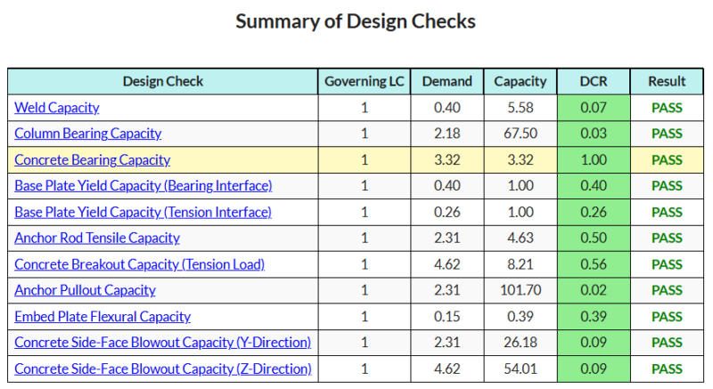
Αγορά λογισμικού πλάκας βάσης
Αγοράστε την πλήρη έκδοση της μονάδας σχεδιασμού πλάκας βάσης από μόνη της χωρίς άλλες ενότητες SkyCIV. Αυτό σας δίνει ένα πλήρες σύνολο αποτελεσμάτων για σχεδιασμό πλάκας βάσης, συμπεριλαμβανομένων λεπτομερών αναφορών και περισσότερων λειτουργιών.

