
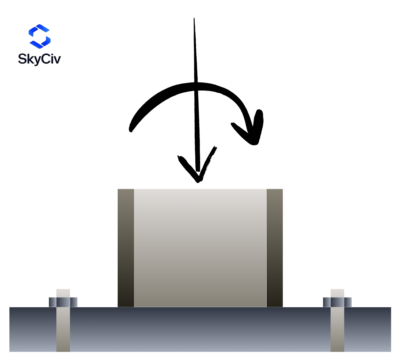
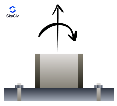
Base Plate Design for Axial Load and Moment
Base plate design for axial load and moment depends on the magnitude and direction of the applied loads. The calculation procedure changes depending on whether the connection is governed by compression, ένταση, or a combination of axial load and bending moment. Calculations from one case cannot always be reused in another, so the first step is to identify which category your design falls into.
Οδηγός σχεδίασης AISC 1 (3έκδοση) is the main reference for designing base plates with moment loads. It includes all the equations and a step-by-step calculation procedure. οπότε όποιο μέρος της δομής θέλετε να σχεδιάσετε produces a calculation set for designing base plates subjected to moment loads, following the procedures outlined in AISC DG1.
Set 1: Combined Axial Compression and Bending (Χαμηλή στιγμή)
When a base plate is loaded with moment, it may seem that the plate will tip to one side. Ωστόσο, when the compression load is large, the eccentricity (the moment divided by the axial load) can remain within the critical eccentricity of the connection. Σε αυτήν την περίπτωση, the applied load is resisted entirely by bearing on the concrete, and the anchors carry no uplift force. This is the most ideal case for base plate design, since the anchors act only as holding-down bolts.
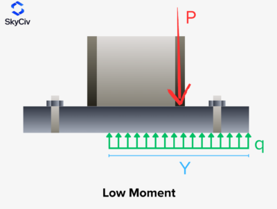
Design checks needed for Low Moment Case (Συμπίεση + Κάμψη):
- Ρουλεμάν από σκυρόδεμα
- Base plate yielding at the bearing interface
Set 2: Combined Axial Compression/Tension and Bending (Μεγάλη Στιγμή)
If the eccentricity is larger than the critical eccentricity, that is the axial load is relatively small compared to the moment load, the base plate tends to tip over, with compression on one side and tension on the other. The anchors must have enough tensile capacity to resist the induced uplift force. This can occur with compression and bending, or with tension and bending.
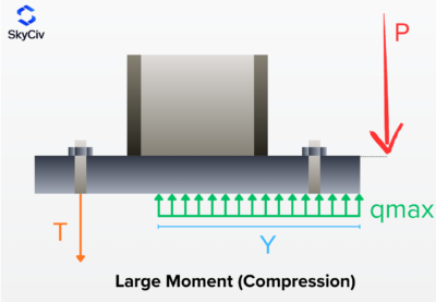
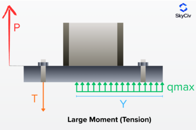
Design checks needed for Large Moment Case (Συμπίεση + Bending or Tension + Κάμψη):
- Ρουλεμάν από σκυρόδεμα
- Base plate yielding at the bearing interface
- Base plate yielding at the tensile interface
- Anchor checks for tension
Set 3: Combined Axial Tension and Bending (Χαμηλή στιγμή)
Base plates may also carry tension and moment. Although this is less common, it is still a possible scenario. It applies when the eccentricity from the tension and moment loads is small enough that the plate does not behave as a large moment case. Εδώ, all of the anchors are in tension. Several methods are available for distributing the force among the anchors and are worth reviewing as further reading.
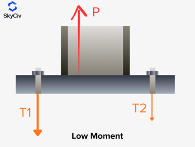
Design checks needed for Low Moment Case (Ενταση + Κάμψη):
- Base plate yielding at the tensile interface
- Anchor checks for tension
For more information on anchors checks with tension, check this documentation on anchor design per ACI 318-19.
Calculate Base Plate Design Loads with SkyCiv
Λογισμικό σχεδιασμού πλάκας βάσης SkyCIV performs the calculations described above, including concrete bearing, base plate yielding, anchor tension, and other connection checks. Select the design code, enter the column and loading conditions, and generate the design results directly in your browser.
