
Exemple de conception de plaque de base utilisant AISC 360-22 et ACI 318-19
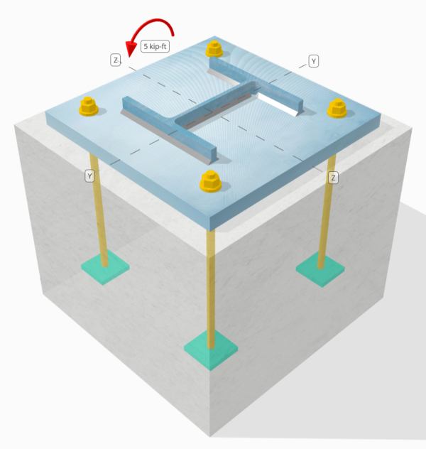
Déclaration de problème
Déterminez si la connexion de colonne à base de colonne conçue est suffisante pour un 5 kip-ft strong-axis moment.
Données données
Colonne:
Section colonne: W8x31
Zone de colonne: 9.130 in2
Matériau de colonne: A992
Plaque de base:
Dimensions de la plaque de base: 15 en x 15 in
Épaisseur de plaque de base: 1 in
Matériau de plaque de base: A36
Béton:
Dimensions du béton: 18 en x 18 in
Épaisseur de béton: 15 in
Matériau en béton: 3000 psi
Soudures:
Taille de soudure: 1/4 in
Classification du métal de remplissage: E70XX
Charge de compression transférée par les soudures uniquement? NON
Modèle dans l'outil gratuit SkyCiv
Modélisez la conception de la plaque de base ci-dessus à l'aide de notre outil en ligne gratuit dès aujourd'hui.! Aucune inscription requise.
Determine if Low Moment or Large Moment
The calculations for this base plate example, which is subjected to a strong-axis moment, will be based on Guide de conception AISC 1, 3édition rd. According to the design guide, base plates subjected to moment loads only are classified as the Large Moment Case. This is because no axial load is present to counteract the eccentric load acting on the connection.
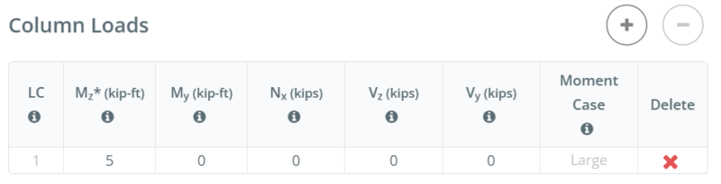
For other load combinations, such as strong-axis bending with axial compression or strong-axis bending with axial tension, determining if the case is Large Moment or Low Moment depends on the actual taille de colonne, base plate size, concrete size, and the given de charges.
In the free version of SkyCiv, the moment case is displayed as you enter the load values. You can access the free tool here to determine the moment case yourself. Straight from the browser, aucune installation requise.
To learn more about Low Moment and Large Moment case, refer to this SkyCiv article: AISC DG1: Plaques de base avec grand moment et faible moment
Calculs étape par étape
Vérifier #1: Weld capacity
We start the design by checking the weld capacity of the connection. We use the Blodgett equations from Conception de structures soudées par Omer W.. Blodgett to determine the weld section modulus of the weld. We take the weld shape shown below as a simplification.
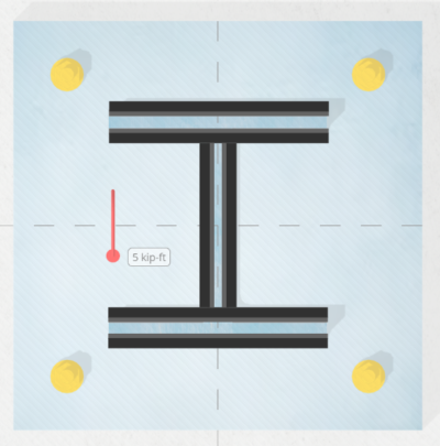
\(S_w = 2d_{col}b_f + \dfrac{(d_{col})^2}{3} = 2 \times 8 \text{ in} \times 8 \text{ in} + \dfrac{(8 \text{ in})^2}{3} = 149.33 \text{ in}^2\)
Prochain, we divide the applied bending moment by the weld section modulus to determine the weld stress per unit length. Note that in calculating the weld section modulus, we assume the critical weld stresses occur at the outermost fiber. For a weld in an I-shaped section, the critical locations are at the outer flanges. We get the weld stress as:
\(r_{uw} = \dfrac{M_z}{S_w} = \dfrac{5 \text{ kip·ft}}{149.33 \text{ in}^2} = 0.40179 \text{ kip/in}\)
ensuite, on calcule le capacity of the weld. Pour un 0.25 in weld size, the design weld throat is 0.177 in, which is obtained by multiplying the weld size by \(\dfrac{\sqrt{2}}{2}\). En utilisant AISC 360-22 Eq. J2-4, the weld capacity per unit length is:
\(\phi r_n = \phi 0.6F_{exx}E_w k_{ds} = 0.75 \times 0.6 \times 70 \text{ ksi} \times 0.177 \text{ in} \times 1 = 5.5755 \text{ kip/in}\)
Puisque 0.40179 kpi < 5.5755 kpi , the column weld capacity is suffisant.
This weld check investigates the weld stress at the tension flange. Since the geometry is symmetric and the only load is a moment acting at the center, we can assume the stress at the compression flange is the same as the stress at the tension flange. Par conséquent, the welds at the compression flange also have enough capacity.
Dans cet exemple de conception, toutefois, the design inputs specify that compression is not transferred through the welds, but through palier. C'est à dire, in the next check, we evaluate the bearing capacity of the column.
Vérifier #2: Calculate column bearing capacity
After evaluating the weld capacity, we make sure the column has enough capacity to bear on the base plate. This is necessary because we assume the welds do not carry the compression load.
Première, Nous déterminons le compressive stress at the critical section, which is still the flange. We then add any contribution from axial compression. Dans le cas présent, there is none.
\(r_u = \dfrac{N_x}{A_{col}} + \dfrac{M_z 0.5d_{col}}{I_{zz,col}} = \dfrac{0 \text{ kip}}{9.13 \text{ in}^2} + \dfrac{5 \text{ kip·ft} \times 0.5 \times 8 \text{ in}}{110 \text{ in}^4} = 2.1818 \text{ ksi}\)
ensuite, nous utilisons AISC 360-22 Section J7 Eq. J7-1 pour déterminer le capacité portante:
\(\phi r_n = \phi 1.8F_{y\_col} = 0.75 \times 1.8 \times 50 \text{ ksi} = 67.5 \text{ ksi}\)
Puisque 2.1818 KSI < 67.5 KSI, La capacité de roulement de colonne est suffisant.
Habituellement, this check is not governing.
Vérifier #3: Calculer la capacité de roulement en béton
To calculate the concrete bearing capacity, we need two areas. See the figure below as a guide.
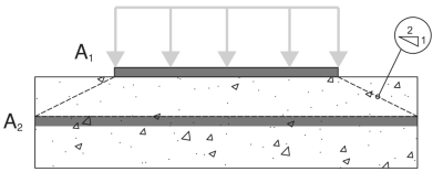
- A1 – Base plate loaded area
- A2 – Area of the concrete support with the same shape as A1
A1 est le loaded area of the base plate, tandis que A2 est le same loaded area projected at a 2H:1V slope into the concrete support. More details on these areas can be found in ACI 318-19 Section 22.8.3.2.
Dans ce base plate design with moment, the A1 area will be calculated using the full width of the base plate, \(B\) et la actual bearing length, \(Y\). The actual bearing length is measured from the edge of the base plate at the compression side towards the center of the plate.
\( A_1 = B \times Y \)
For most engineers, calculating A1 and A2 requires a lot of work, so they simply assume A1 = A2, ce qui est conservateur. Dans le Logiciel de plaque de base Skyciv, itérations are performed to determine the actual A1 values and to maximize the capacity of the base plate.
The table below shows the iteration steps from SkyCiv to determine the bearing length Y, et par la suite, to determine the actual A1 and A2 areas.

Première, an initial Y is assumed, and the A2 and A1 values are calculated based on the initial Y. These are then used to calculate the maximum bearing strength of the concrete, \(f_{p\_max}\), et le correspondant bearing force per unit length, \(q_{max}\). Once these are determined, the corresponding Y value is determined based on Eq. 4-32 of AISC DG1 3rd Édition. If the calculated Y does not match the initial Y, another iteration step is performed. A more detailed step-by-step calculation of the last iteration is shown in the next section.
Maintenant, taking the A2 and A1 values from the iteration, nous utilisons Eq. 4-2 of AISC Design Guide 1, 3édition rd, to determine \(f_{p\_max}\), the design bearing strength for concrete crushing:
\(f_{p\_max} = \phi \left( \min \left( 0.85 \, (f_c’) \sqrt{\dfrac{A_2}{A_1}}, \, 1.7 \, (f_c’) \right) \right)\)
\(f_{p\_max} = 0.65 \times \left( \min \left( 0.85 \times (3 \text{ ksi}) \times \sqrt{39.941}, \, 1.7 \times (3 \text{ ksi}) \right) \right) = 3.315 \text{ ksi}\)
Aussi, since this design is a Large Moment Case, the base plate has both a compression side and a tension side. Dans cette situation, we should allow the concrete bearing to be at its full capacity and minimize the Y value. Donc, any remaining tensile force, based on equilibrium of forces, will be taken by the anchors at the tension side.
Given this, we set \(f_{p\_actual}\) égale à \(f_{p\_max}\).
\(f_{p\_actual} = f_{p\_max} = 3.315 \text{ ksi}\)
Puisque 3.315 ksi ≤ 3.315 KSI, La capacité de roulement en béton est suffisant.
Vérifier #4: Calculate base plate yielding capacity at the bearing interface
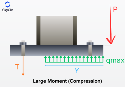
The next step is to determine if the base plate has enough capacity for the given load. As the moment load pushes the base plate against the concrete, the base plate has a tendency to yield due to flexure. We call this check the base plate yielding check on the bearing interface. There is also a separate yielding due to the tension load, and it will be covered in the next design check.
To check the base plate yielding, we need to determine the \(q_{max}\), which is the compression force per unit length. AISC DG1 3rd Ed. Eq. 4-37 donne \(q_{max}\)comme:
\(q_{max} = f_{p\_max}B_{bp} = 3.315 \text{ ksi} \times 15 \text{ in} = 49.725 \text{ kip/in}\)
ensuite, we will calculate the Y-dimension. Although the Y-dimension is already calculated in the prior check, this section will show how we use the equations from AISC DG1. For this Large Moment Case, nous utilisons Eq. 4-32 of AISC DG1, 3édition rd.
For the plus case:
\(Y_{case1} = \left( f + \dfrac{L_{bp}}{2} \right) + \sqrt{\left( \left( f + \dfrac{L_{bp}}{2} \right)^2 \right) – \dfrac{2M_z}{q_{max}}}\)
\(Y_{case1} = \left( 5.5315 \text{ in} + \dfrac{15 \text{ in}}{2} \right) + \sqrt{\left( \left( 5.5315 \text{ in} + \dfrac{15 \text{ in}}{2} \right)^2 \right) – \dfrac{2 \times 5 \text{ kip·ft}}{49.725 \text{ kip/in}}}\)
\(Y_{case1} = 25.97 \text{ in}\)
For the minus case:
\(Y_{case2} = \left( f + \dfrac{L_{bp}}{2} \right) – \sqrt{\left( \left( f + \dfrac{L_{bp}}{2} \right)^2 \right) – \dfrac{2M_z}{q_{max}}}\)
\(Y_{case2} = \left( 5.5315 \text{ in} + \dfrac{15 \text{ in}}{2} \right) – \sqrt{\left( \left( 5.5315 \text{ in} + \dfrac{15 \text{ in}}{2} \right)^2 \right) – \dfrac{2 \times 5 \text{ kip·ft}}{49.725 \text{ kip/in}}}\)
\(Y_{case2} = 0.092925 \text{ in}\)
Note that this equation has + et – symboles, so we get two values. D'ici, we need to determine which value makes more sense. Puisque 25.97 in is greater than the base plate length, 15 in, we will not consider this value. Donc, nous utiliserons 0.092925 in comme le longueur du roulement.
\(Y = Y_{case2} = 0.092925 \text{ in}\)
Prochain, we calculate the cantilever lengths. Voici les m and n dimensions from the figure below. Ceci est basé sur AISC DG1 3rd Edition Section 4.3.1.
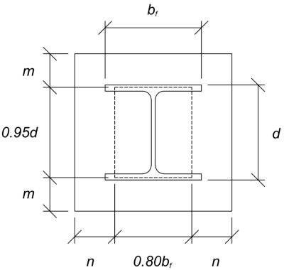
The calculated m and n cantilever values are:
\(m = \dfrac{L_{bp} – 0.95d_{col}}{2} = \dfrac{15 \text{ in} – 0.95 \times 8 \text{ in}}{2} = 3.7 \text{ in}\)
\(n = \dfrac{B_{bp} – 0.8b_f}{2} = \dfrac{15 \text{ in} – 0.8 \times 8 \text{ in}}{2} = 4.3 \text{ in}\)
ensuite, On le fera compare the calculated Y value to the larger of m and n. Since Y is less than the larger cantilever length, nous utiliserons AISC DG1 3rd Ed. Eq. 4-52a. This gives the required base plate thickness to be:
\(t_{p(req)} = \sqrt{\dfrac{4f_{p\_actual}Y \left( n – \dfrac{Y}{2} \right)}{\phi F_{y\_bp}}}\)
\(t_{p(req)} = \sqrt{\dfrac{4 \times 3.315 \text{ ksi} \times 0.092925 \text{ in} \times \left( 4.3 \text{ in} – \dfrac{0.092925 \text{ in}}{2} \right)}{0.9 \times 36 \text{ ksi}}} = 0.4022 \text{ in}\)
Ensuite, let’s compare it to the actual base plate thickness.
\(t_{p(actual)} = t_{bp} = 1 \text{ in}\)
Puisque 0.4022 in < 1 in, the yielding capacity of the base plate is suffisant.
Vérifier #5: Calculate base plate yielding capacity at the tension interface
The required tensile force on the anchors at the tension side Viagra Féminin Pour Acheter Du Viagra À Base De Plantes 🎚️🕖⠠ Pharmacie Sans Ordonnance to the resulting compression force on the compression side. This is because the base plate is only loaded with moment loads, and so the resulting couple forces are equal in magnitude.
To calculate the required strength of anchors, nous utilisons AISC DG1 3rd Ed. Eq. 4-31.
\(T_u = q_{max}Y = 49.725 \text{ kip/in} \times 0.092925 \text{ in} = 4.6207 \text{ kip}\)
ensuite, on calcule le eccentricity of this tensile force from the column support. This is taken from the center of the anchor rod to the center of the column flange. Nous utilisons Eq. 4-61 of the design guide to determine the eccentricity. In the equation, f is the distance of the anchor rod from the column centerline.
\(x = \left( f – \dfrac{d_{col}}{2} \right) + \dfrac{t_f}{2} = \left( 5.5315 \text{ in} – \dfrac{8 \text{ in}}{2} \right) + \dfrac{0.435 \text{ in}}{2} = 1.749 \text{ in}\)
Note that in this analysis, we take the whole base plate width as the section to resist the flexure, as we closely follow the AISC DG1 3rd Ed. guidelines. Other conservative bending widths could also be used.
Ensuite, we determine the required base plate thickness utilisant Eq. 4-62a.
\(t_{p(req)} = \sqrt{\dfrac{4T_u x}{B_{bp}\phi F_{y\_bp}}} = \sqrt{\dfrac{4 \times 4.6207 \text{ kip} \times 1.749 \text{ in}}{15 \text{ in} \times 0.9 \times 36 \text{ ksi}}} = 0.25791 \text{ in}\)
Puisque 0.25791 in < 1 in, l' yielding capacity of the base plate is suffisant.
Vérifier #6: Vérifications d'ancrage
The rest of the anchor design checks are not shown in this example. Please refer to other SkyCiv Base Plate Design Examples that covers capacity of ancrage.
Résumé de la conception
Le logiciel de conception de la plaque de base SkyCiv peut générer automatiquement un rapport de calcul étape par étape pour cet exemple de conception. Il fournit également un résumé des contrôles effectués et de leurs ratios résultants, rendre les informations faciles à comprendre en un coup d'œil. Vous trouverez ci-dessous un échantillon de tableau de résumé, qui est inclus dans le rapport.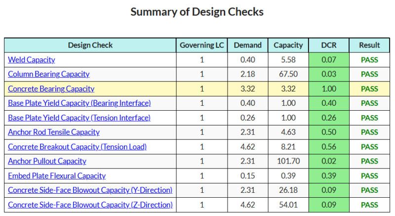
Logiciel d'achat de plaques de base
Achetez la version complète du module de conception de la plaque de base seul sans aucun autre module Skyviv. Cela vous donne un ensemble complet de résultats pour la conception de la plaque de base, y compris des rapports détaillés et plus de fonctionnalités.

