How to Design an Aluminum Structure using ADM, AS1664, Eurocode or CSA 157
The tutorial will show how you can design as a standalone, or integrated with SkyCiv Structural 3D.
Today we will be exploring how we can model and design an aluminium frame, using SkyCiv Structural 3D, as shown in our aluminum design example below.
Standalone Aluminium Design – Optional
The first part of the video shows how SkyCiv users can perform simple design checks on their aluminium members using our standalone Quick Design software. This is beneficial where users:
- Just need to run a single member, or few members
- Already know their design forces and want to run a simple check
The Quick Design module (which is available from the SkyCiv Dashboard, under Quick Design) where users can select from the following supported aluminum structure design standards:
- American Standards – Aluminum Design Manual (ADM) 2015 (ASD & LRFD)
- Australian Standards – AS/NZS 1664
- Canadian Standards – CSA 157-17
- British/Eurocode – BS/EN 1999-1-1:2007
Once selected your required design standard, the user interface is very easy to follow; with clear inputs, tooltips for user directions and a clear output panel on the right hand side:
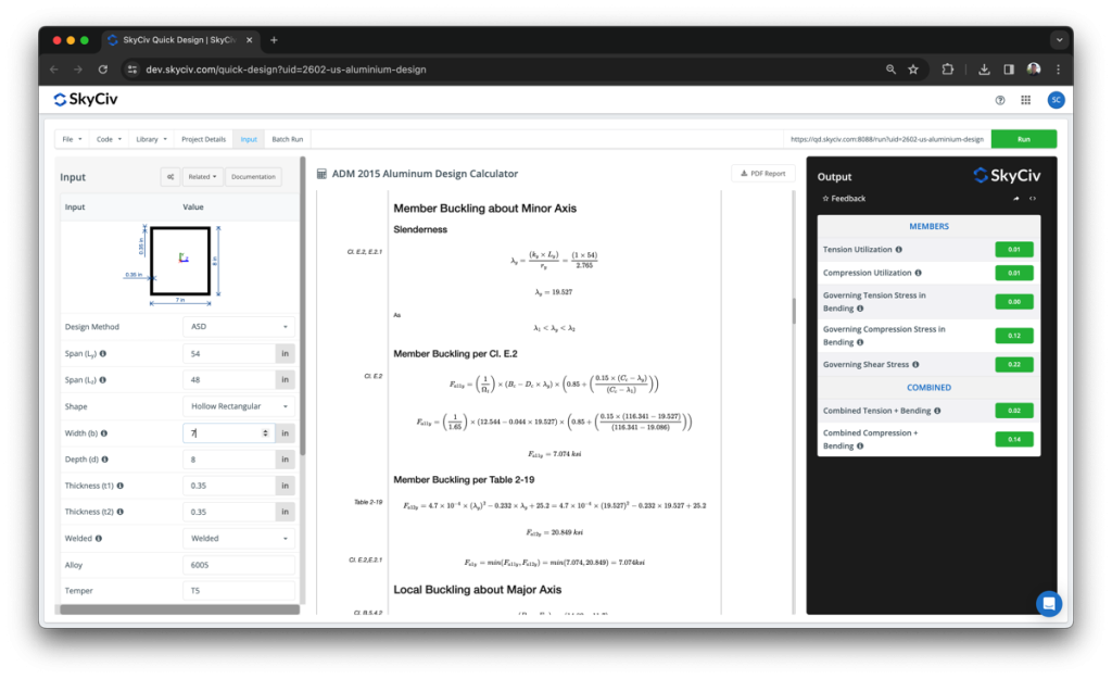
This is the same calculation base that will be used on the integrated SkyCiv Structural 3D version. However, this one will use your S3D model as the basis of your design – importing all loads, section properties, material properties and member lengths automatically from your analysis results.
Modelling your Aluminium Structure
Now, let’s get started with the aluminum design example! As mentioned, the integrated aluminium structure design software is fully integrated with SkyCiv Structural Analysis Software. As with most of our other supported design standards, this starts with the model.
Today we’re building the model via the following steps:
- Build the model in 2D using the pen tool
- Use the Repeat function to copy this out 8 times
- Apply supports
- Define members as different section IDs by selecting them and mass-editing them on the left panel
- Apply some area loads for dead loads/live loads
- Import some Load Combinations from ASCE 7-16
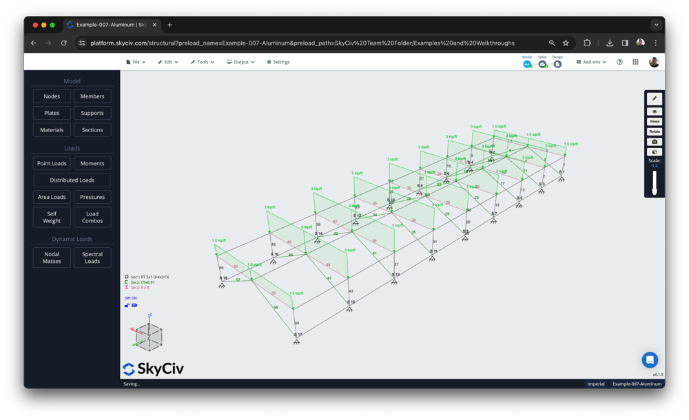
The final result should look something like this:

Importing Aluminium Materials and Sections from the Database
SkyCiv has pre-populated a lot of the materials and sections used by these design standards to make input faster for our users. For instance, the software includes sections and material properties for the following common countries and manufacturers:
- ADM Database of sections and materials
- Australian welded and non-welded sections and materials from AS1664
- Altus aluminium materials
- CSA S157-17 materials
- EN 1999 2007 welded and non-welded materials
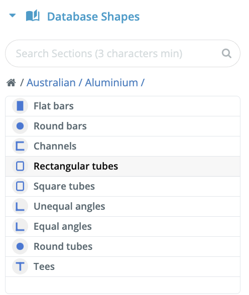
Once you have your model built, you can assign the various section IDs with actual sections from the database using the SkyCiv Section Builder. Simply click the section you wish to define, then the Builder button. Under database you should see a list of sections. For instance, here is our supported Australian AS1664 section database:
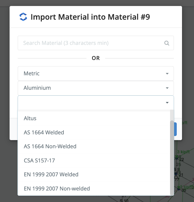
Once your section is selected, you’ll need to pick a material to assign to it. On the right panel click Add Material, which will give you a list of materials to select from (or use the powerful search function). For instance, here’s a list of our supported material database for metric units:
These material and section properties will be automatically pulled into the integrated design module for a completely seamless design process.
Running the Integrated Design
You’re now ready to solve! Click Solve and once that’s done, click Design. This will ask you which design module to select. Under Other – Aluminium, you can then open up your relevant design standard. This will automatically launch the module, importing all your members and worst-case design forces which are shown on the left Input table. The check is automatically run, with governing utility ratios highlighted clearly to show passing and failing members:
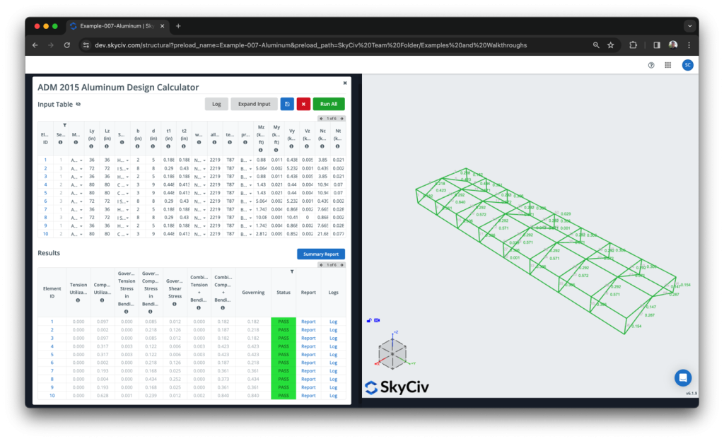
While importing, there’s also a log which will give you more information about what has been imported into the module. For instance, if you see some grey elements which you believe should have been imported, they may have been skipped because they were (a) the wrong material type (b) a non-supported shape. These will show themselves in the log and give you more information to help you repair these issues.
Reporting
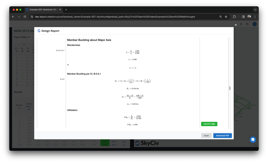
The design is all run in one go, however you can open up the individual design reports to dive deeper into the calculations and understand the full calculations better. This matches the one in the standalone module, here’s an example calculation from our ADM design check:
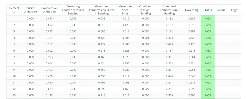
You can also export a more concise design report summary of your entire model. This is a shorter report with a simple table showing the design inputs and the pass/fail results:
FAQ
1. What if some of my members didn’t import?
The module will import any members that:
- Have their material class set to aluminium
- Are a supported section shape (I Beam, Channel, HSS, Hollow Circular)
Check your material ID is set to aluminium to troubleshoot
2. What section shapes are supported?
- I Beam
- Hollow Circular
- Hollow Rectangular
- Channel
- Custom Shapes (AS1664 Only)


