Simple Structural Analysis Model
Learn the basics of using SkyCiv, including modelling, applying loads and running a structural analysis of a simple frame. In this example, we’ll look at a simple steel frame and perform a buckling analysis to determine whether the steel structure is buckling.
If this is your first time using SkyCiv, or are new to structural analysis, this is a great tutorial and example structure to build!
The User Interface
SkyCiv Structural Analysis Software has made the user interface clean and intuitive, with clear buttons and options clearly available to the user. Here are the main parts of the software:
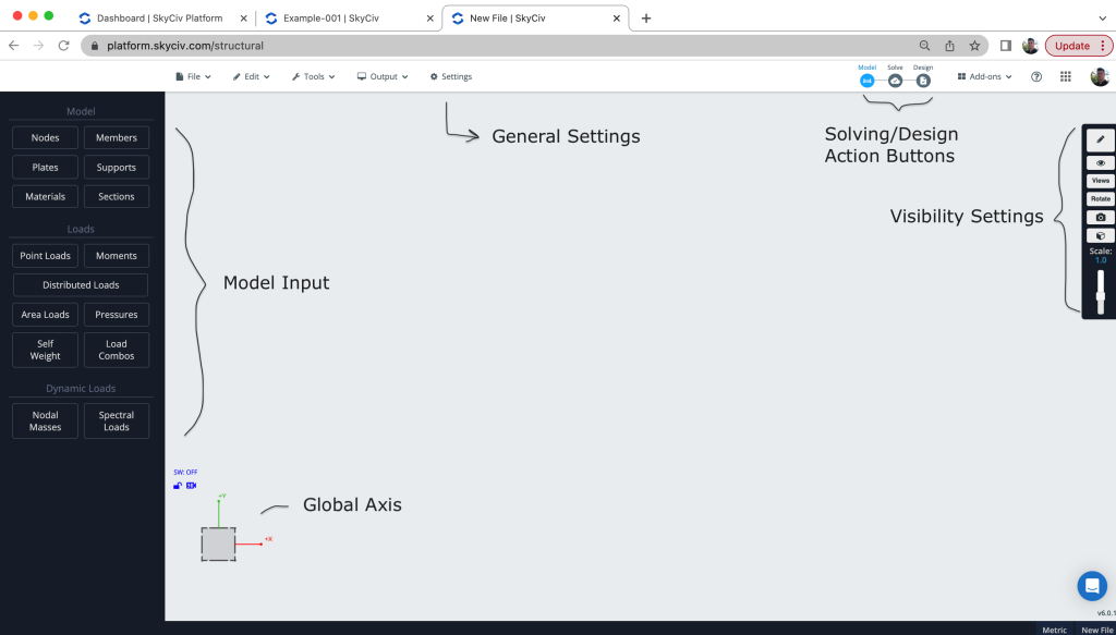
The user interface also has info tips, making it easier to understand the settings and options. You can even search using CTRL + F to locate elements and features.
Modelling
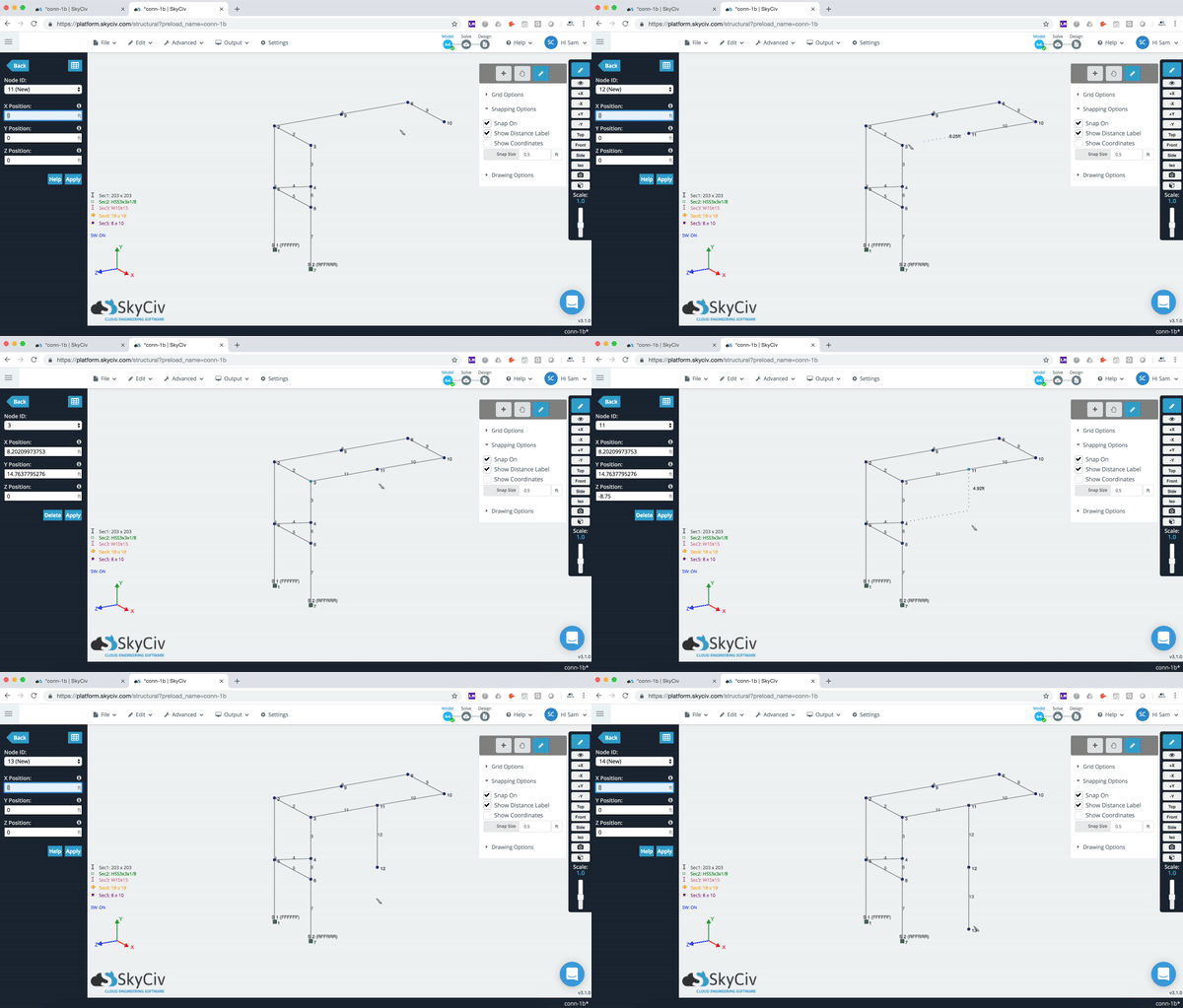
Modelling typically starts with nodes. Nodes represent the start/end position of a member, the outline of plates or location of supports. You can model nodes using manual input, datasheets, importing from CSV or even using our Pen Tool:
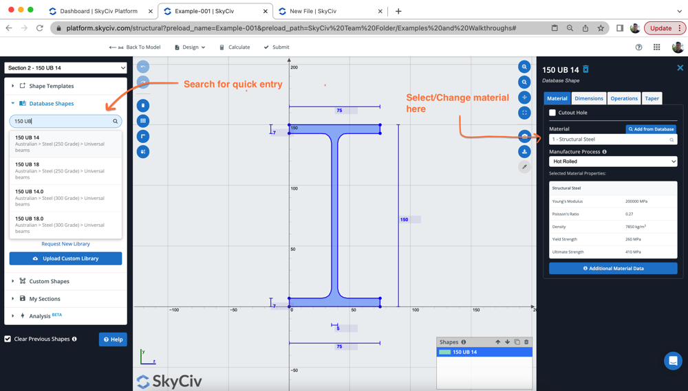
Once nodes and members are built, we will apply some section properties to the structure. This can include manual input, but more commonly, the user will launch the SkyCiv Section Builder Software to either create a template shape, load from a library, or build your own custom shape. In this case, we loaded an HSS section from the Australian Library:
Supports provide restraint to your structure, ensuring your model is stable. Insufficient restraints or supports will cause the structure to be unstable and therefore cause solving issues.
Applying Loads and Load Combos
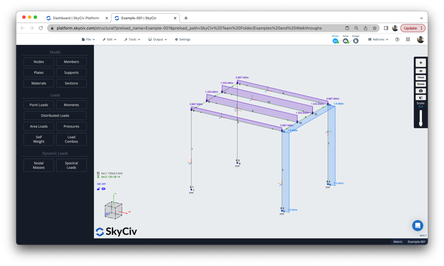
Once you have built your structure, it’s time to apply some loads! Users can apply point loads, distributed loads or in this example, Auto area loads that auto calculate the tributary area and auto-adjust as your model changes! Here is the loads we apply to our sample model, with a one-way area load (set as a live load, in purple) and some distribute forces to the members (set as Wind Loads, in blue):
For more information on this step, there is a great explainer video on Load Groups and Load Combinations on our YouTube Channel.
Running a Structural Analysis and Reviewing the Results
The model is now ready to solve. We currently support the following solving options:
- Linear Static (including Plates)
- Non Linear (P-delta and p-delta)
- Buckling Analysis
- Response Spectrum Analysis
- Frequency Analysis
The software will automatically create Envelope (worst case) load combinations and make all your load combinations available from the top left corner. After selecting your load combination, you can display the results for the various internal stresses, support reactions, bending, shear, deflection and much more… Here is an example of isolating the beam shear force diagrams:
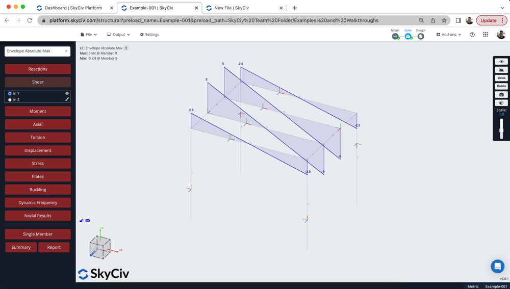
Results are all based on the member’s local axis system as demonstrated in the video. The user can also view a report summary or export a full analysis report.
FAQ
Yes, using the same steps as shown in the video the user can just as easily design for a different material. When specifying the Section, simply change the Material ID and assign it to another material (for instance concrete or timber).
Continuous Members: these are set by default, and will automatically detect and connect to any nodes along this member. This makes modelling easier, as you can have a single member that is still connected at various points (without splitting the member)
Normal Member: Are only connected and the start and end of the member. Any intersecting nodes will not connect to this member.
More Info: Normal vs Continuous Members
A quick test to see if this is an issue, is to simply set all your restraints and members to FFFFFF (fully fixed) and see if that resolves your stability issues.
Stability issues can also be caused if members aren’t connected properly. A quick and easy way to see this is to solve the structure, turn on deflections and scale the loading up and down to animate the deflection.
We also have a repair model function, that will check a lot of common modelling issues. Run this under Operations – Repair Model.
Finally, you can review the list of errors for common issues, or watch this video on 6 ways to troubleshoot your model.
Related tutorials
- Intro to Structural 3D
- A guide to Loads, Load Cases and Load Combinations – with Video
- A guide to Buckling – with Video
- One Way Area Loads


