Introduction
In the following tutorial, we will explore how to create a Concrete Structure using SkyCiv Structural Analysis, beginning with the modeling, analysis, and designing of a structure.
We will go step by step showing how to create nodes, members, plates, sections, materials, supports, loads, and load combinations.
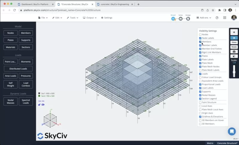
You have to open Structural 3D from your SkyCiv dashboard and create a new project, in this tutorial, we will be working on meters, so you can modify the units by going to settings > unit system and selecting metric
Member creation
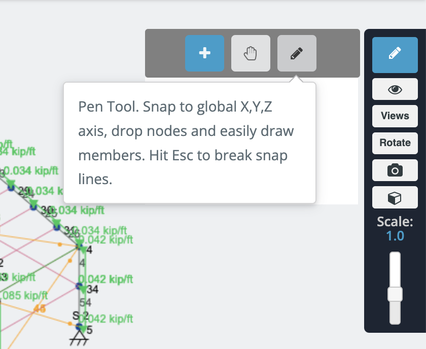
There are different ways to create members, using the form, and datasheet, but in this example, we will be using the pen tool for the member creation, you can activate the pen tool going to the right panel > pen > pen tool.
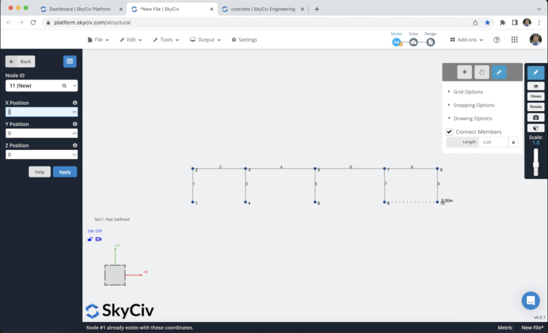
After we have the pen tool selected we can start to create all the frame members we will create a column member of 5m, and beams of 8m and 10.5m, then connect all the members as shown in the following image:
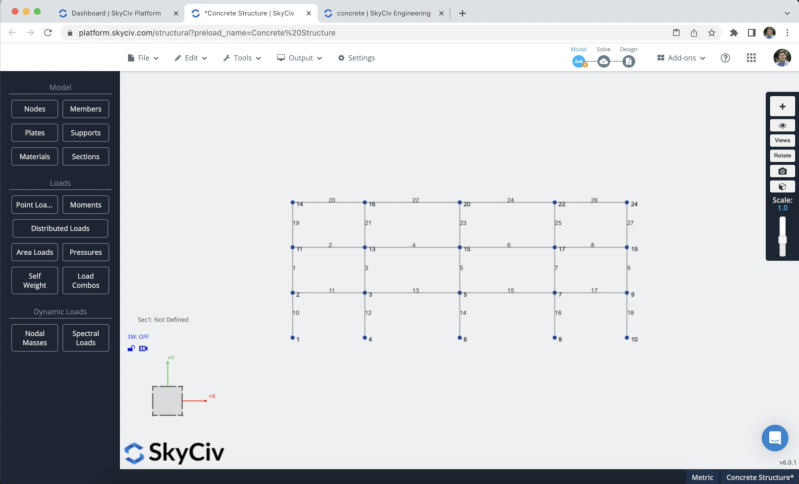
The next step will be to replicate these members, we can select the structure using Ctrl + A and then hit Ctrl + C, select node id:2, and hit Ctrl + V we will repeat this process 2 times. The result should look like this:
To avoid the creation of more nodes and members we will duplicate the frame that we created in the previous steps in the Z axis. To achieve this we need to select the whole structure by doing right click on the canvas > Select all or hit Ctrl + A on your keyboard. After we select the whole frame we can go to Edit > Operations > Repeat or hit Ctrl + D.
A form will appear on the screen, we will use the information shown in the following image:
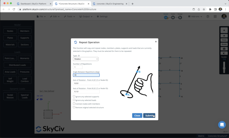
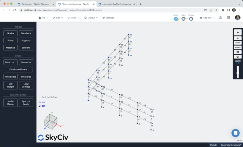
We will use one repetition with an angle of 90 degrees. The result should look as shown in the following image:
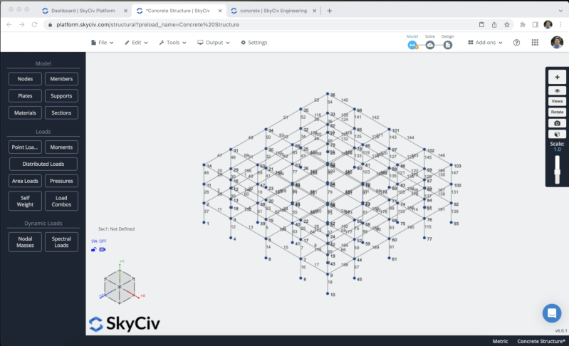
We can proceed and copy all the members to complete our structure.
Sections and Materials
The next step will be the creation of sections and materials, in this example, we will be using the Section Builder module to create our sections, to access the Section Builder module we need to go to Sections > Builder. Once the section builder is opened, we can select sections from Shape Templates, in this case, we will select Shape Templates> Rectangular and we will define a section of 600×600 for our columns. We can modify the material to Concrete on the right Panel.
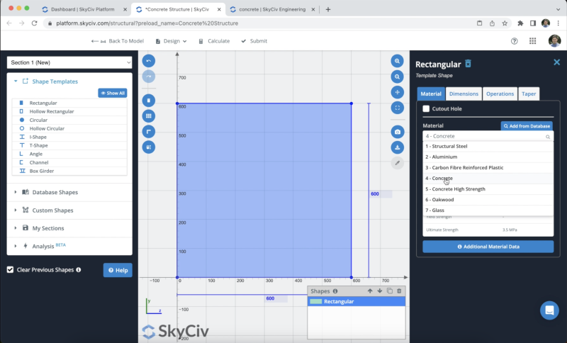
After we select our section we can click on Submit. By default, when we have members without sections defined, the new section will be assigned to them. If we open the 3D renderer we will see the following result.
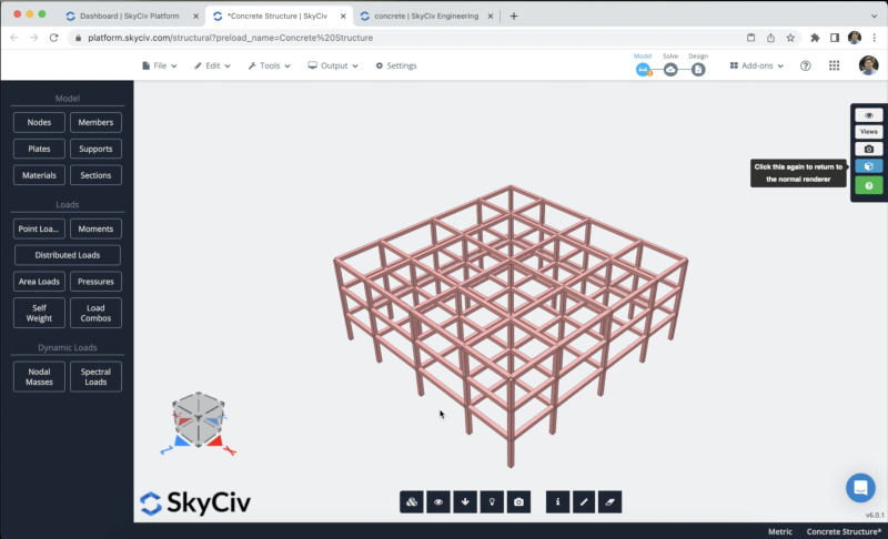
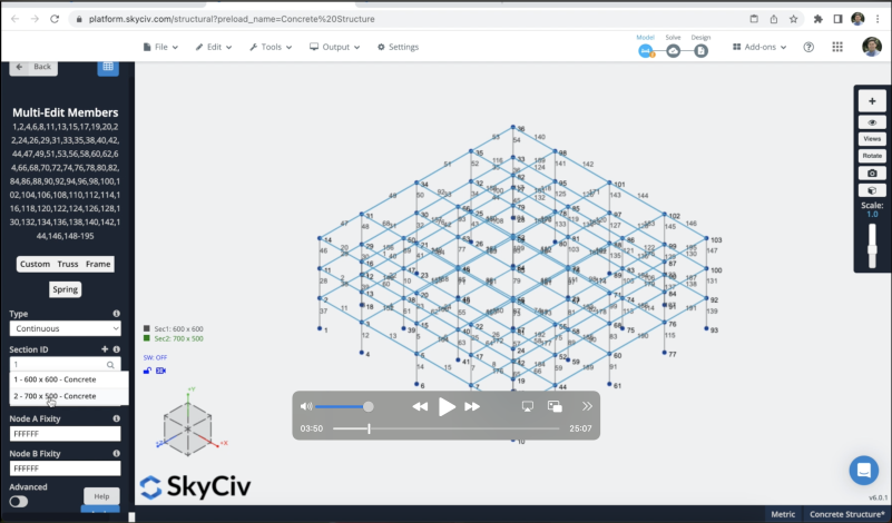
However, we want to use different sections for our beams in this case, we will repeat the same process creating a 500×700 concrete section in Section Builder. When we finish the creation, we need to select all the beams, next step will be to modify the section of these members to the one created for our beams and click on Apply.
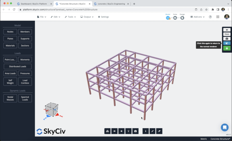
The result of our sections should look like this:
Walls and Slabs
When can create plates in Structural 3D to create our walls and slabs, we can use the button called Plates to create them, however, in this case, we just have to select 4 nodes, do right click > Add Plate.
For this example, we will simulate an elevator to create our walls and will create slabs on our three floors.
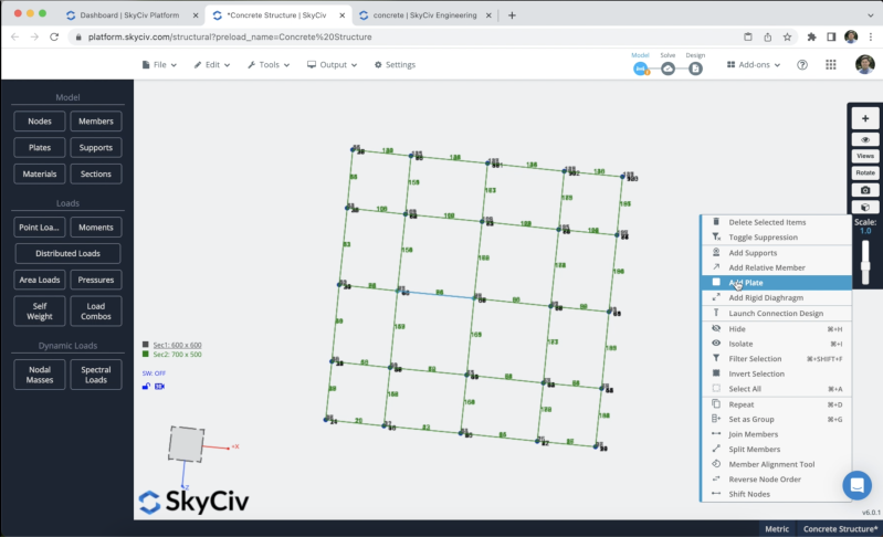
After we finish the process, we can select our plates and modify their thickness and materials, in this example, we will be using 15 mm for our walls and 10 mm for the slabs. After we create all of our plates, the result should look like this:
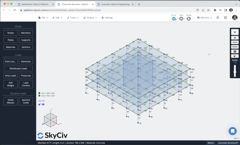
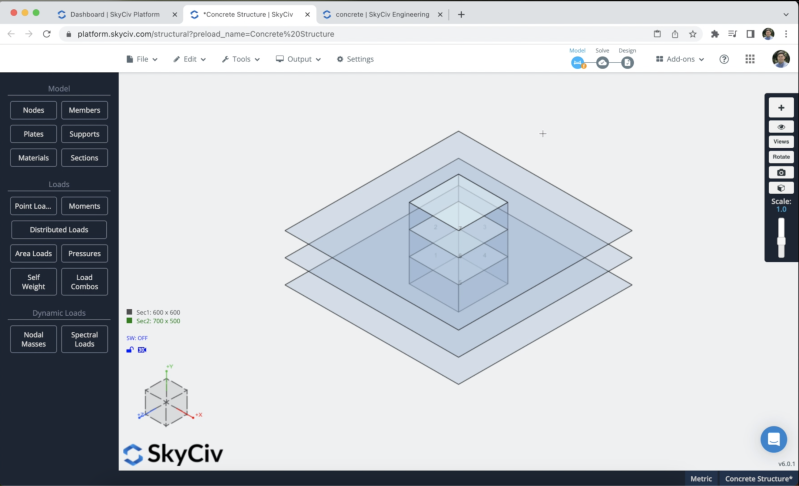
We can also, create holes in our slabs, in this case, we can select a plate > right-click> Plate hole > insert the nodes that we want to use in our hole and submit. We can do the same process for all of our slabs to create the elevator hole.
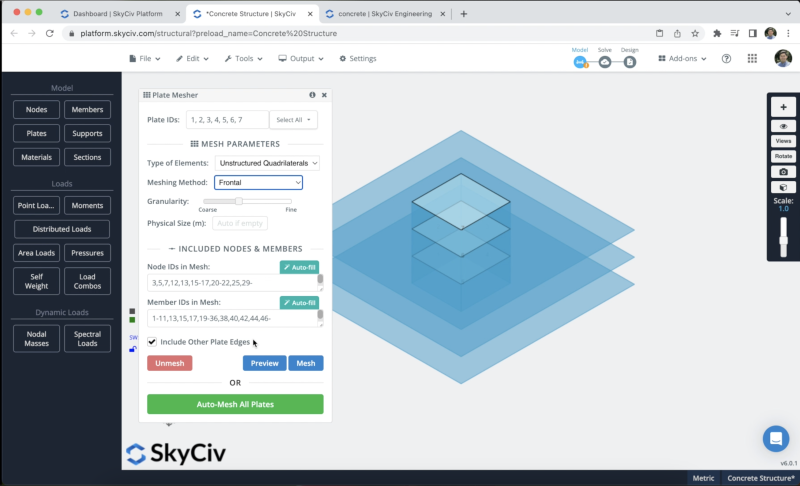
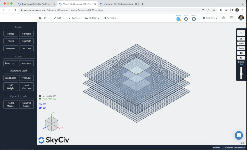
To create our meshed plates, we can select all of our plates > right click > Mesh Plate, then we can use the following information in the form, finally we can click on Mesh.
Loads Assignment
We will apply some area loads to our structure, we will use live loads on all the floors and self weight on our members. To apply live loads you can go to Area Loads and put the following data (Put the 4 nodes where you want to apply your area load):
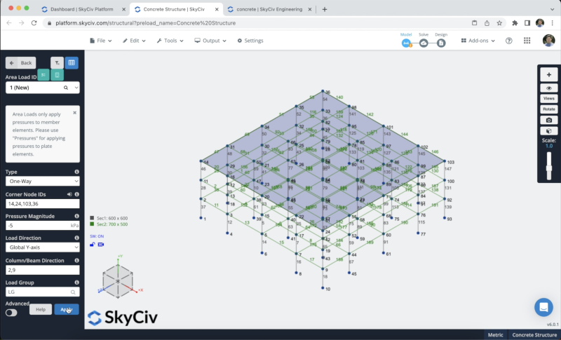
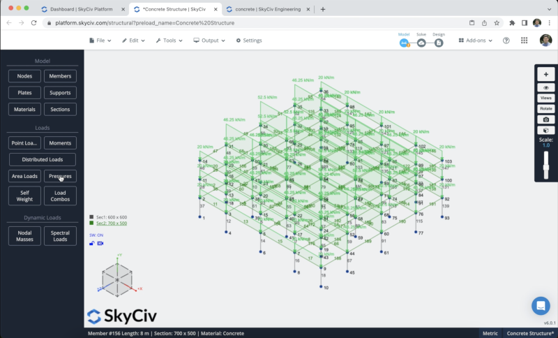
We will repeat the same process with the remaining floors. The final result should look like this:
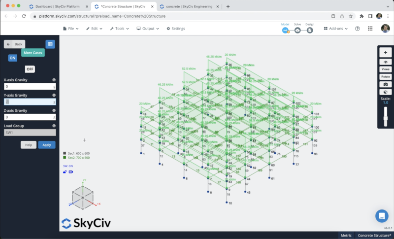
We will activate the self-weight of our members so when we solve our structure the load of the elements will be considered, to do this we just need to click on Self Weight > Click on On > Apply. We need to verify that the value in our vertical axis is equal to -1.
Supports Assignment
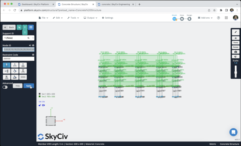
To add supports to our structure we have to select all the ground nodes, then go to Supports > Double Click on the Node ID field (If you have your nodes selected) > Select 3D Pin Support > Apply. After you create all your supports they should appear on your model.
Load Combinations
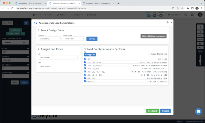
We can define know our load combinations, we need to click on Load Combos > Design Codes, and a window containing the design codes from the database should appear, we will use the ACI318-2011 code for this example and we will click on Display.
When the load combinations appear, we need to ensure that the names that we use to define our area loads and self-weight correspond to loads of the code. When you have your loads defined you can click on Import and all the load combinations should appear on the datasheet.
Solving the Model
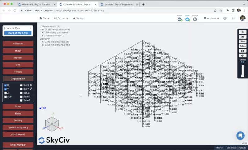
After we finished the modeling of the structure, we can proceed to solve our Structure, we can do this by clicking on Solve > Linear Static, and it will take us to a new window where we will be able to see all the results of the members.
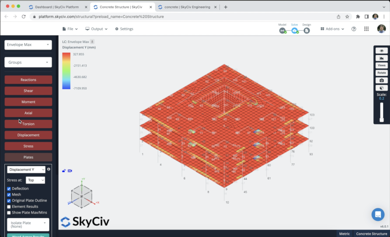
We can also check the results of our slabs and walls by clicking on the Plates section:
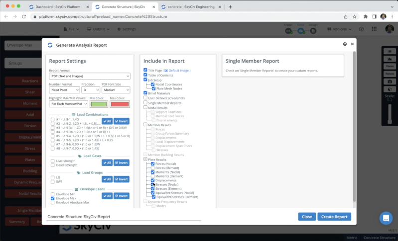
We can also create reports from the analysis, we can click on Report, customize the report as needed, specify what load combinations to include, etc. We can click on Create Report when we finish the configuration.
Members design
We can now run the design checks of our structure, we can click on Design Check > Start New Code > RC Member Design > Select ACI 318-19 > Start. Once, everything is correct, you can modify member parameters, Reinforcement layouts, etc. In this example, we will use the optimize option, which will optimize our designs in our columns and beams.
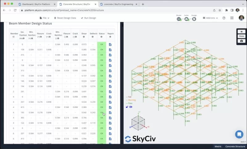
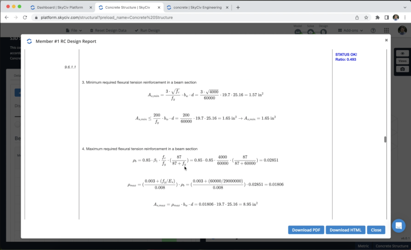
We can check the report for each of our sections to see all of the calculations done in the design checks.
Slabs design
We can now run the design checks of our slabs, we can click on Design Check > Start New Code > RC Plate Design > Select ACI 318-19 > Start. Once, everything is correct, you can modify slab parameters, materials/factors, etc. We need to define Strength and Serviceability combinations to make the calculations. In this example, we will define a portion of our slab to show the process of design.
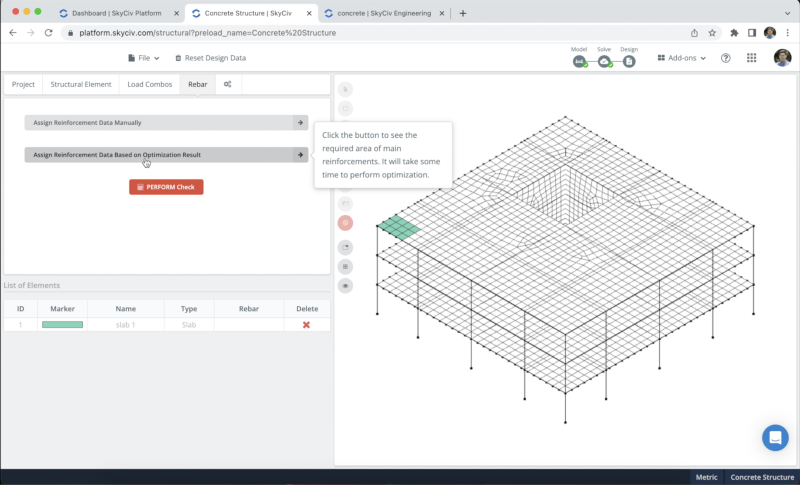
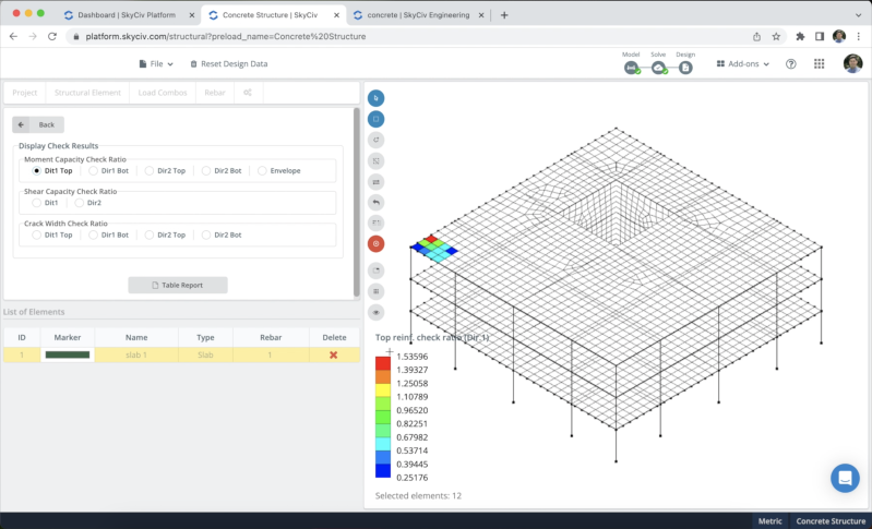
Now that we have our slab selected, we will use the Assign Reinforcement Data Based on Optimization Result option, to assign reinforcement to our plate, we can see all of the results for any direction, and the program will tell us how much reinforcement we need to design our slab. After we define reinforcement in any direction, we will be able to see the checks after clicking on PERFORM check.
FAQ
1. Can I modify the rebar layouts in my design?
Yes, you can modify your rebar layouts in RC member design and in RC plate design.
2. Can I use a diaphragm in my model?
Yes, you can refer to the following link to use diaphragms.
3. Can I design walls in RC plate design?
At the moment, we have the option of slabs design only.


