australiane / Standard della Nuova Zelanda 4600 per strutture in acciaio a freddo, 2018 Edizione
L'AS/NZS 4600:2018 module checks cold-formed steel members with the Metodo della forza diretta. It runs in SkyCiv Structural 3D and supports custom restraints along each member.
Per il 2005 edition, vedere AS4600 Member Design.
With this module you can:
- Run design checks to AS/NZS 4600:2018 with the Direct Strength Method, Compreso:
- Member pre-qualification
- Axial tension
- Axial compression: section capacity, and member capacity for global, local and distortional buckling
- Bending about both axes: section capacity, and member capacity for lateral-torsional, local and distortional buckling
- Shear along both axes
- Combined bending and shear
- Compressione e flessione combinate
- Tensione e flessione combinate
- Design channels, Z sections, hat sections, back-to-back channels and lipped channel boxes, prismatic or non-prismatic
- Define custom restraints and pseudo-restraints along each member
- Export detailed step-by-step PDF reports
- Controlli di taglio (Run Designer) to find the most efficient section
Current version support
sezioni
- o scanalatura
- Canale a labbro
- Lipped Channel single
- Sezione Z
- Lipped Z
- Edizione The American Iron and Steel Institute
- Back-to-back Channels
- Back-to-back Lipped Channels
- Scatola del canale lipped
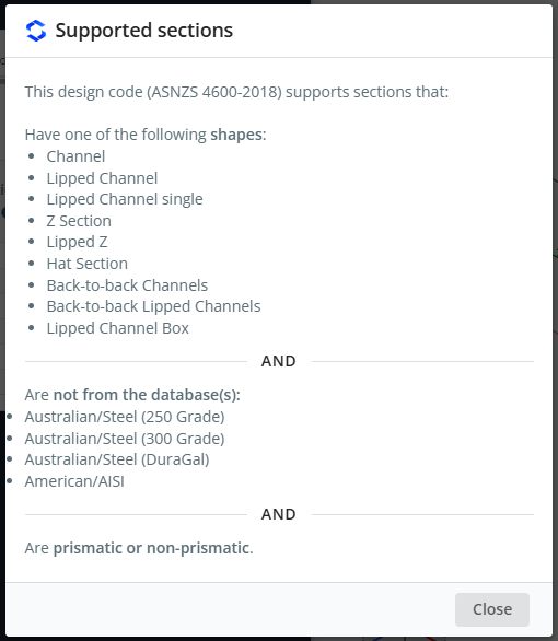
Back-to-back lipped channels and lipped channel boxes are supported only by this code. Sections can be prismatic or non-prismatic, and the material must be steel. Sections must not come from the Australian/Steel (250 Grado), Australian/Steel (300 Grado), Australian/Steel (Caro) or American/AISI databases.
To see this list in the software, open the log and click View supported sections.
Software
- SkyCiv Structural 3D
AS / NZS 4600-2018 is also listed in the Codice di progettazione dropdown of SkyCiv Beam. This page describes the module in SkyCiv Structural 3D.
Nota
Units must be in metrico to use this design module. In the Model, Aperto impostazioni (top bar) > unità and set the unit system to metrico.
Opening the module
- Solve the model.
- Clic Design in the top bar.
- Nel Select a Design Module, scegliere Membro in acciaio formato a freddo.
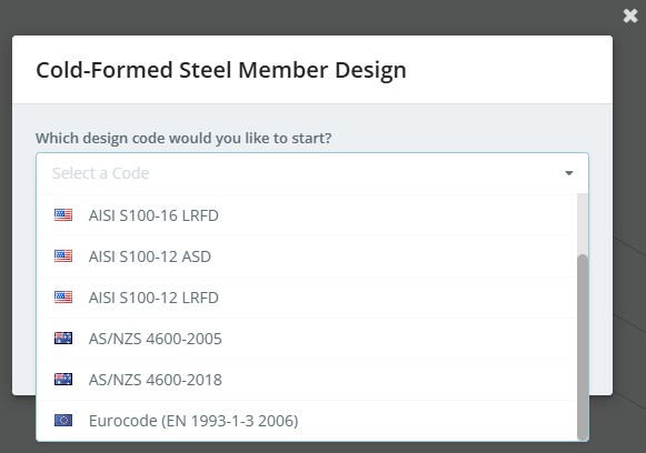
- Nel Which design code would you like to start?, pick AS / NZS 4600-2018, quindi fare clic Inizio.
If a design module is already open, uso Cambia modulo nel Design menu to switch codes.
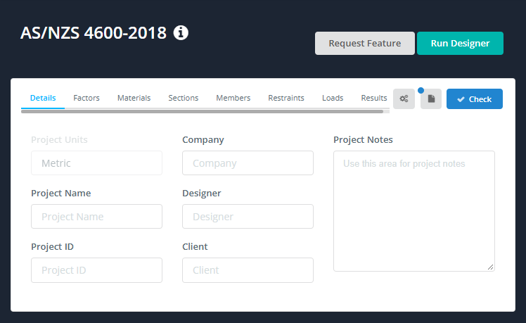
The design panel opens on the left, with the 3D model on the right. The header shows the code, plus Request Feature e Run Designer. On the right of the tab bar are three buttons:
- the settings (gear) pulsante, which opens Member Design Settings
- the log button, which opens the Member Design Log
- Dai un'occhiata, which runs the design check
When the module starts, an alert may tell you that there are important messages. They are shown in the Member Design Log, for example "6 members were loaded with default values", or members that were not imported because their section or material isn’t supported. The log has a View supported sections collegamento.
The tabs are Dettagli, Fattori, materiale, sezioni, Membri, Restrizioni, Carichi e risultati.
Member Design Settings
Click the gear button to open Member Design Settings. It has one option:
- Checks based on geometric axes instead of principal axes: unchecked by default. It affects the capacity of sections that are not symmetric about both axes, such as Z sections.
As the dialog notes, engineering guidance should be used when you change these settings. Clic Salva to apply.
Dettagli
Sul Dettagli tab you can enter the project details. You don’t have to fill them in, but anything you enter is shown in the Dettagli del progetto table of your reports. Project Units shows metrico and can’t be changed here.
Fattori
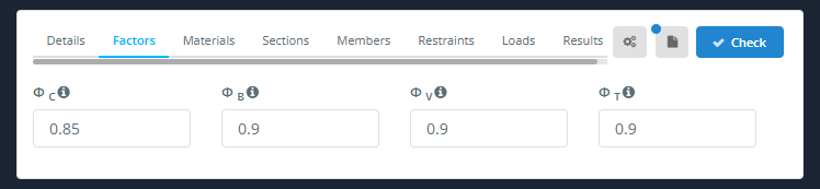
La Fattori tab shows the capacity reduction factors:
| Fattore | Descrizione | La resistenza alla compressione sarà considerata come da AS4600 |
|---|---|---|
| B = Profondità o diametro della sezioneC | Compressione | 0.85 |
| B = Profondità o diametro della sezioneB | Flessione | 0.9 |
| B = Profondità o diametro della sezioneV | cesoia | 0.9 |
| B = Profondità o diametro della sezioneT | Tensione | 0.9 |
If a member is not pre-qualified (Clausola 1.6.3(c)(io)), B = Profondità o diametro della sezioneC, B = Profondità o diametro della sezioneB and ΦV are reduced to 0.8. The factors used for each member are listed in its report under Strength Limit State Factors, with their clause references.
materiale
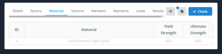
La materiale tab lists the materials used by the designed members, with their Forza di rendimento e Massima forza. The table is filled in from the model and can’t be modified here. To change a material, go back to the Model.
sezioni
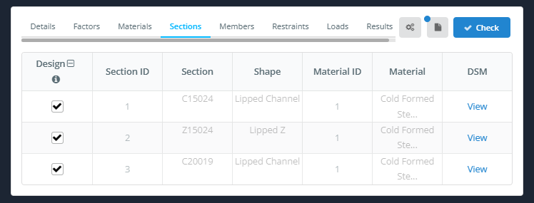
La sezioni tab lists the sections used by the designed members. The section data comes from the model and can’t be modified here.
- Design: tick the box to design the members that use this section. The icon in the column header toggles all rows.
- ID sezione, Sezione, Forma, ID materiale e Materiale: taken from the model.
- DSM: clic Visualizza to see the DSM factors of the section.
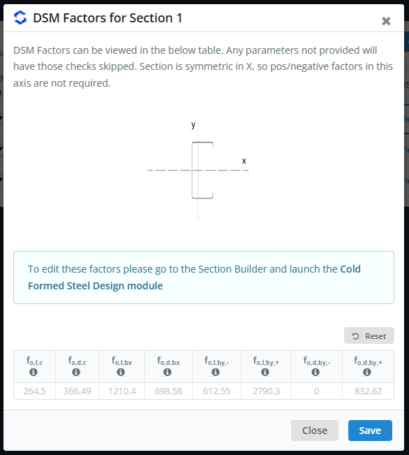
La DSM Factors for Section n dialog shows a sketch of the section with its axes, and the elastic buckling stresses (in MPa) used by the Direct Strength Method:
| Simbolo | Buckling stress |
|---|---|
| fIl,l,c | Instabilità locale, compressione |
| fIl,d,c | Instabilità distorsiva, compressione |
| fIl,l,bx | Instabilità locale, bending about x |
| fIl,d,bx | Instabilità distorsiva, bending about x |
| fIl,l,di,- e fIl,l,di,+ | Instabilità locale, bending about y (negativo e positivo) |
| fIl,d,di,- e fIl,d,di,+ | Instabilità distorsiva, bending about y (negativo e positivo) |
Any factor that is not provided has its check skipped. For a section that is symmetric about an axis, the positive and negative factors about that axis are not needed. The values can’t be edited here: to change them, vai al Generatore di sezioni and launch the Design in acciaio formato a freddo modulo.
Membri
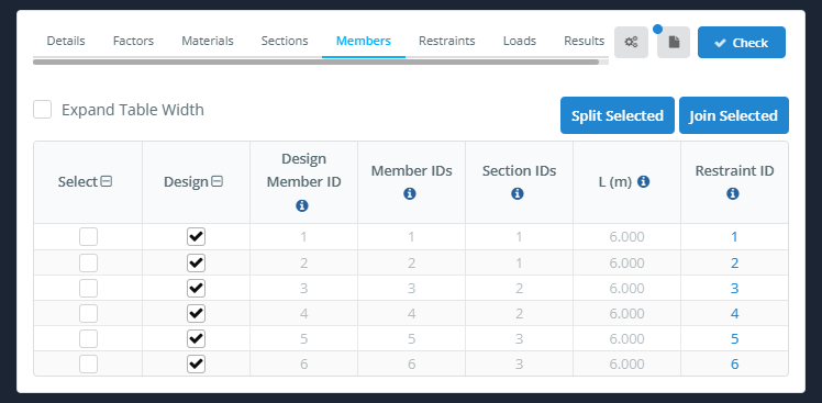
La Membri tab lists the design members. Each design member is made up of one or more model members.
- Expand Table Width: widens the table.
- Split Selected e Join Selected: split the selected design members, or join them into one design member.
| Colonna | Descrizione |
|---|---|
| Selezionare | Ticks the row, for example to split or join members |
| Design | Tick to include the member in the design check, untick to leave it out |
| Design Member ID | The ID of the design member |
| non è necessario identificare la direzione della campata | The model member(S) that make up the design member |
| ID sezione | La sezione(S) of the design member |
| L (m) | The length of the design member |
| Restraint ID | The restraint set used by the member. Click it to open that restraint in the Restrizioni tab |
Design Member ID, non è necessario identificare la direzione della campata, ID sezione e L (m) come from the model and can’t be changed here. Effective lengths and K factors are not entered on this tab: they come from the Restrizioni tab.
Restrizioni
AS / NZS 4600:2018 supports custom restraints, so you can add your own restraints to be used in the calculations. For a full description, see our documentation on restrizioni del membro.
- Gruppo automatico: gives similar members the same restraint ID.
- Restraint ID: selects the restraint ID to view or edit. Use the down and up arrows to go to the next or previous ID.
- Assign to Member(S): assigns the current restraint ID to members.
- Duplicare: copies the current restraint ID to a new ID.
The restraint table is filled in from the model supports and connections. Per esempio, a member supported at both ends gets a row at each end.
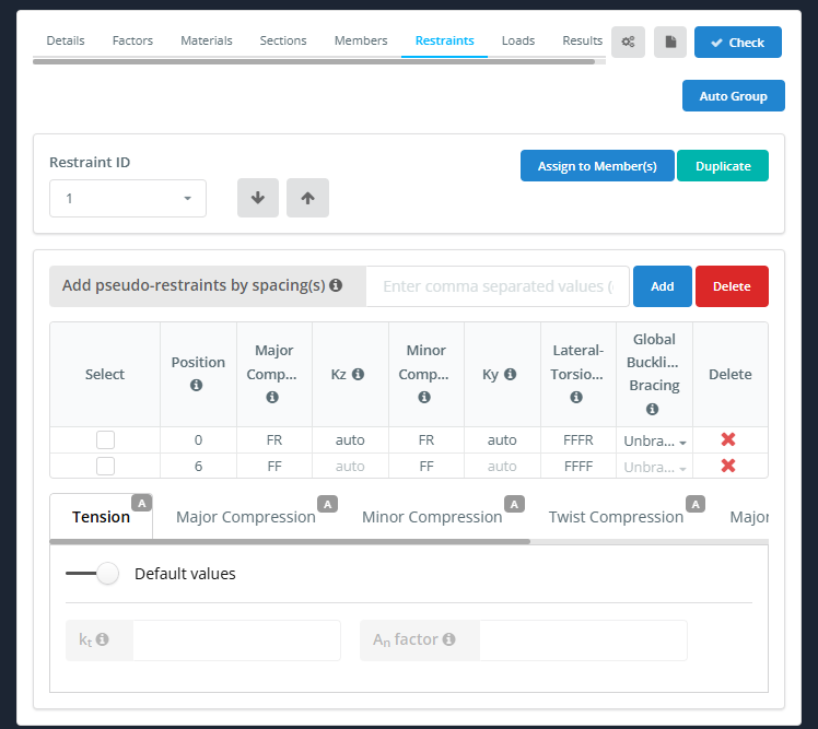
| Colonna | Descrizione |
|---|---|
| Selezionare | Ticks the row, for example to apply a standard restraint to it |
| Posizione | Distance of the restraint from the start of the member |
| Major Compression | 2-key restraint code (F or R) for major-axis flexural buckling |
| Kz | Effective length factor for the major axis (auto per impostazione predefinita) |
| Minor Compression | 2-key restraint code (F or R) for minor-axis flexural buckling |
| Ky | Effective length factor for the minor axis (auto per impostazione predefinita) |
| Laterale-torsionale | 4-key restraint code (F, R or S) for lateral-torsional buckling |
| Global Buckling Bracing | Unbraced, Superiore, Parte inferiore o Tutti e due. If the lateral-torsional restraint fully braces a flange, the global buckling check is skipped for the cases that the bracing covers. Hover over the ℹ icon for details |
| Eliminare | Deletes the restraint row |
Per aggiungere pseudo-restrizioni (restraints that are not modelled), enter the spacings in Aggiungi pseudo-vincoli spaziando(S) e fare clic Inserisci. You can enter a comma separated list (per esempio 1.5,1.5,1.5), use the multiply operator (4*1.5), or use the < operator to fit as many restraints as possible. Clic Eliminare next to Inserisci to remove all the pseudo-restraints.
Pseudo-restraints are added as released (RR e RRRR), so they have no effect until you change their codes. Nell'esempio qui sotto, 4*1.5 adds rows at 1.5, 3 e 4.5 m on a 6 m member, and their Lateral-Torsional code is changed to FFFR.
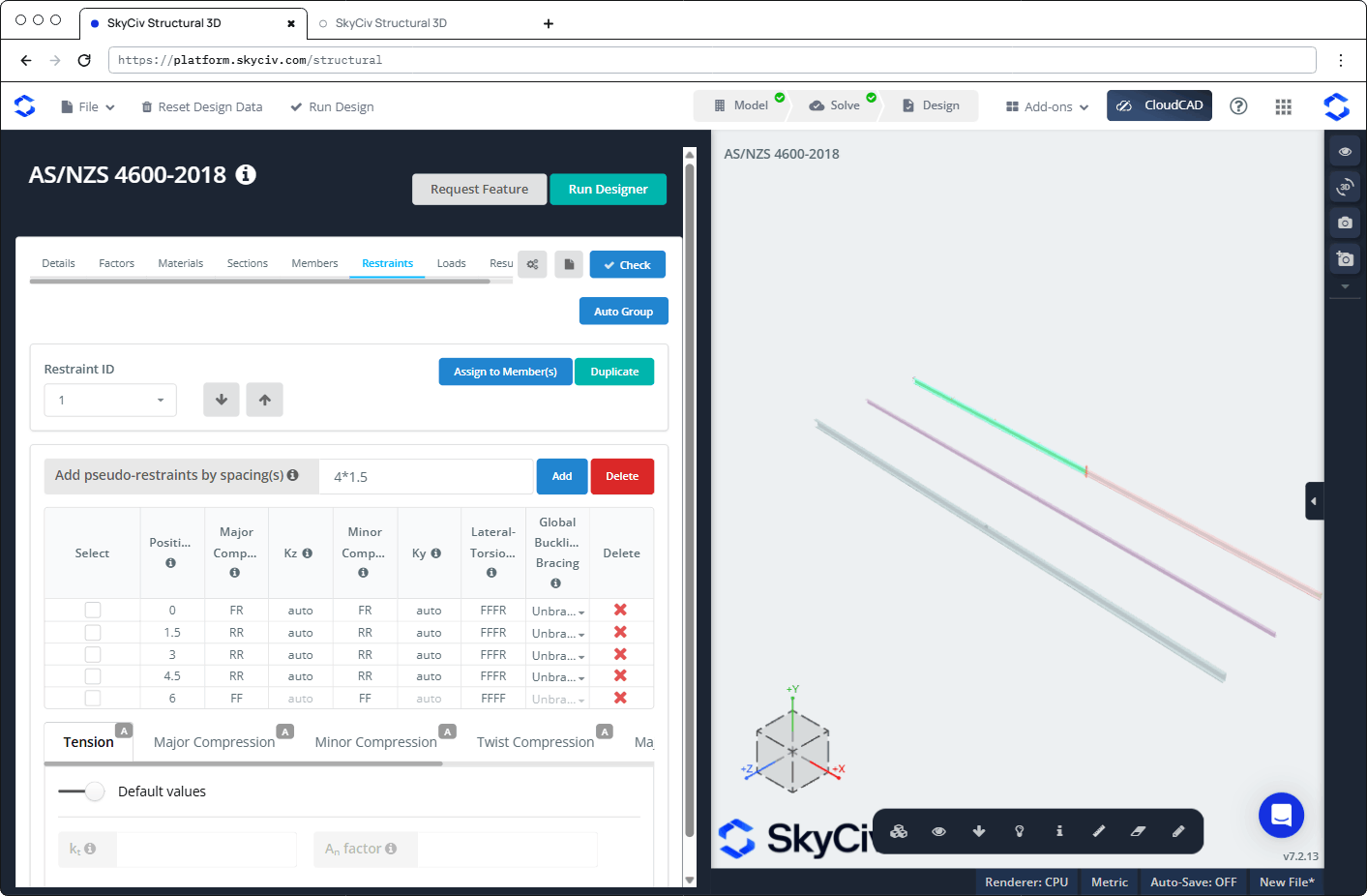
Below the table are sub-tabs, each with an A (automatic) badge by default:
- Tensione: con Default values sopra, the defaults are used. Switch it off to enter your own:
- Kt: correction factor for the distribution of forces in a tension member. The default assumes a non-uniform force distribution, per AS/NZS 4600:2018 Clausola 3.2.3.2.
- An fattore: factor that reduces the gross area to the net area. L'impostazione predefinita è 0.85, which assumes a bolted connection.
- Major Compression (Lz, Kz), Minor Compression (Ly, Ky), Twist Compression (Lx, Kx), Major Lateral-torsional (Lb, KVerifica dell'ACI, Cb) e Minor Lateral-torsional (Lb, KVerifica dell'ACI): per impostazione predefinita, Determine from restraints (as defined in the restraints table) è attivo. Switch it off to enter your own values for the whole member. Sotto Standard Restraints, click an icon to apply a standard restraint to the selected rows.
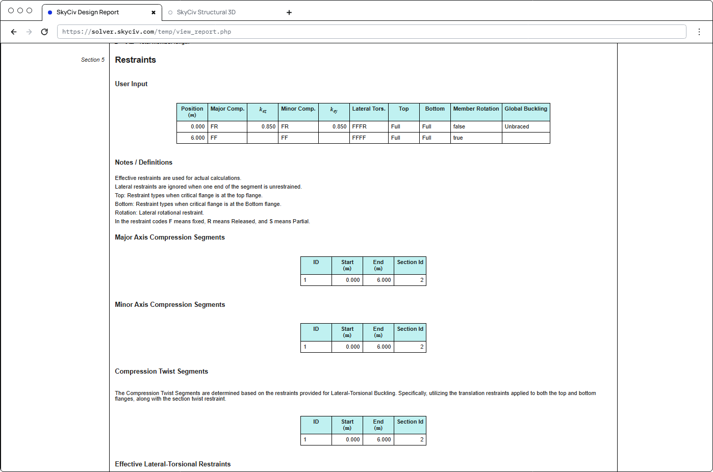
La Restrizioni section of each member report shows the restraints that were used: the user input (posizione, restraint codes, KNo e kehi, top and bottom flange restraint, member rotation and global buckling bracing), the major-axis and minor-axis compression segments, the compression twist segments, the effective lateral-torsional restraints and the segments for each load combination.
Carichi
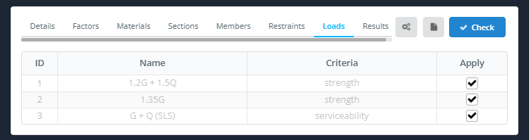
La Carichi tab lists the load combinations from the model, with their Nome e Criteri. Tick Applicare for each load combination you want to include. Serviceability combinations are listed and can be ticked, but no serviceability check is performed.
risultati
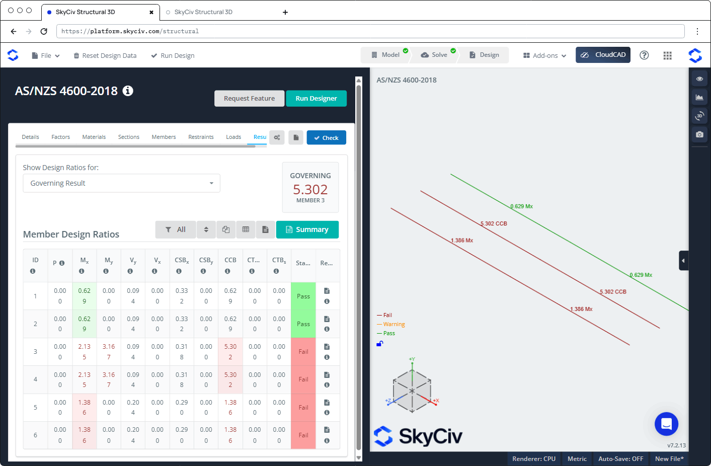
Clic Dai un'occhiata to run the design check. La risultati tab shows:
- Mostra rapporti di progettazione per: chooses which ratios are shown, per esempio Governing Result, Membri falliti, or a single check.
- GOVERNING: the highest ratio and its member.
- A toolbar to filter (Tutto), sort, Specchio, show the table and open the report, di più ha Sommario button for the summary report.
- La Rapporti di progettazione dei membri tavolo, con a Stato (Passaggio o Fallire) e un carico rapporto icon for each member. Hover over the ℹ icon in a column header to see the clause it refers to.
| Colonna | Dai un'occhiata | Clausola |
|---|---|---|
| P | Assiale (tensione o compressione) | 3.2 o 7.2.1 |
| Mx | Bending about x | 7.2.2 |
| My | Bending about y | 7.2.2 |
| V y | Shear along y | 7.2.3 |
| V x | Shear along x | 7.2.3 |
| CSBx | Combined shear and bending, about x | 7.2.3 |
| CSBy | Combined shear and bending, about y | 7.2.3 |
| CCB | Compressione e flessione combinate | 7.2.4 |
| CTBm | Tensione e flessione combinate, member capacity | 7.2.5(1) |
| CTBS | Tensione e flessione combinate, section capacity | 7.2.5(2) |
In the 3D view, each member is coloured Fallire, Avvertimento o Passaggio and labelled with its governing ratio.
Controlli eseguiti
| Dai un'occhiata | AS / NZS 4600:2018 riferimento |
|---|---|
| Member pre-qualification (sets Φ) | Clausola 1.6.3 |
| Axial tension, section capacity | Sezione 3.2 |
| Axial compression, section capacity | Sezione 7.2.1.3 |
| Axial compression, member capacity (globale, local and distortional buckling) | Sezione 7.2.1 |
| Bending about x and y, section capacity | Sezione 7.2.2.3.2 |
| Bending about x and y, member capacity (lateral-torsional, local and distortional buckling), including positive and negative bending about y for singly symmetric sections | Sezione 7.2.2.1 |
| Shear along y (ragnatela) and along x (flangia) | Sezione 7.2.3 |
| Combined bending and shear, about both axes | Eq. 7.2.3(9) |
| Combined axial compression and bending | Eq. 7.2.4 |
| Combined axial tension and section bending capacity | Eq. 7.2.5(2) |
| Combined axial tension and member bending capacity | Eq. 7.2.5(1) |
The module does not check slenderness limits, la deflessione (manutenibilità), web crippling or torsion.
Rapporti
Click the report icon in a member’s rapporto column to open its design report. It opens in a Design Report for Member #n dialog with Close, Apri in una nuova scheda, ScaricaHTML e Scarica PDF pulsanti. The report is titled "AS/NZS 4600-2018 – Direct Strength Method", and contains:
- Dettagli del progetto
- Utilità: every check with its reference, simbolo, description, rapporto e stato
- sezioni: the dimensions and properties of the section
- Stati Limite Ultimi: Prequalificazione dei membri, Strength Limit State Factors, Member Internal Actions, Member and Restraints, followed by each check step by step
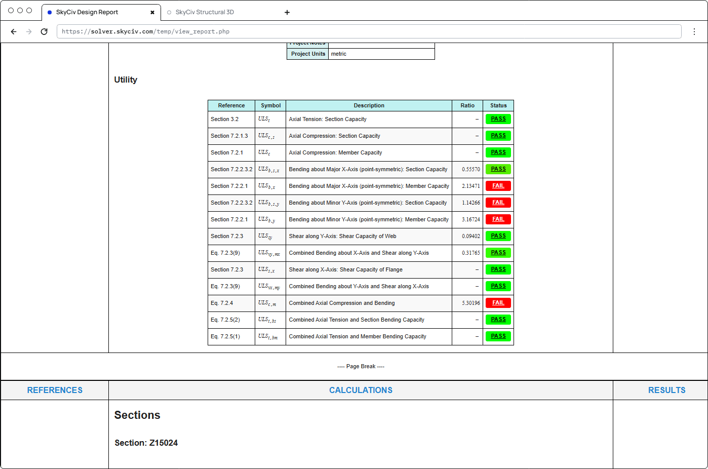
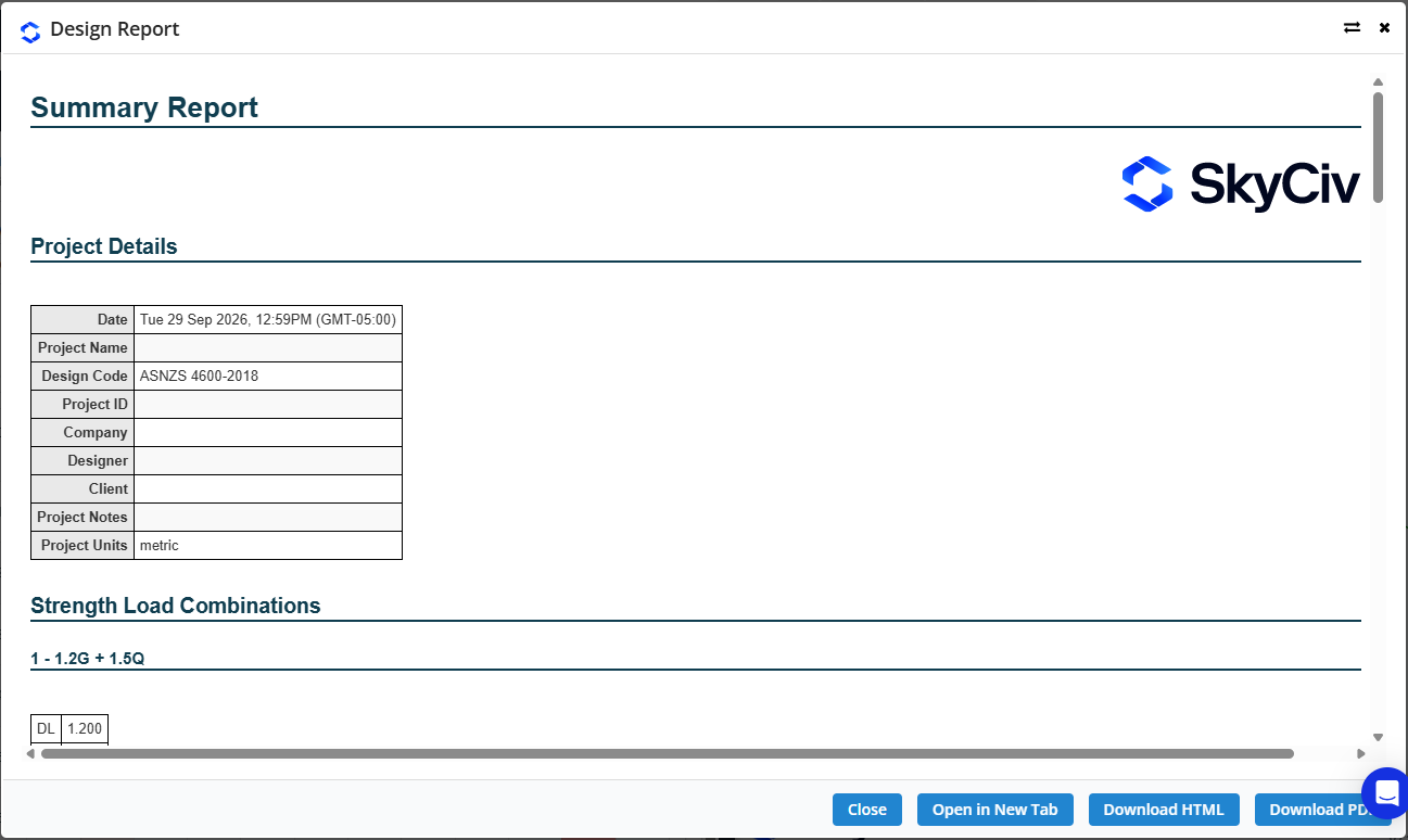
Clic Sommario on the Results tab to open the Relazione di sintesi. It lists the project details (including the design code), the strength load combinations with their factors, and the results for all members.