Introduction
This tutorial will walk you through how to input Fixity Codes using SkyCiv Structural 3D. We will cover how Fixity Codes are defined, the various types of connections, and eventually how to define your own designs in S3D.

Fixity Codes – An Overview
Fixity codes are how we as designers and modelers, are able to tell the program how to handle the transfer of loads between members. The six terms for Member End fixity codes in SkyCiv are used to define the six degrees of freedom at the indicated point and tell the model how to treat the reactions.
- The first term defines the Local X-axis Translation
- The second term defines the Local Y-axis Translation
- The third term defines the Local Z-axis Translation
- The fourth term defines the Local X-axis Rotation
- The fifth term defines the Local Y-axis Rotation
- The final term defines the Local Z-axis Rotation
Member End Fixities
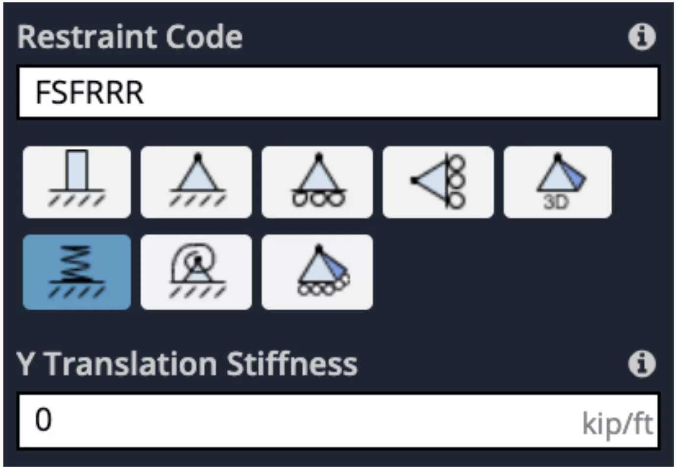
Each term can either be defined as F-Fixed, R-Released, or S-Spring.
Fixed means that the degree of freedom is fixed and the for is transferred to the node. Released means the degree of freedom is not fixed and the force is not transferred. Spring means that the load is being transferred with a stiffness factor that you can define in the settings afterward.
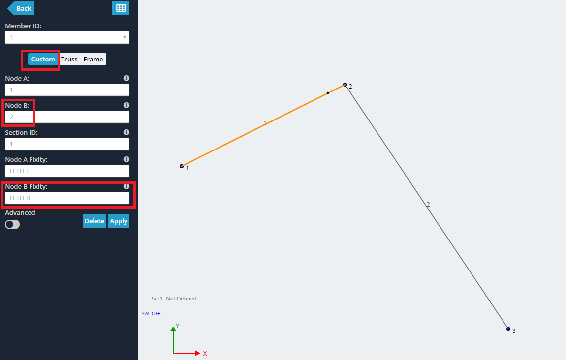
Additionally, you can tell, from inspection whether any of the degrees of freedom in your model are released by looking for a small dot near the end of the member. This is used so you can quickly understand the fixity conditions as you model.


Additionally, you can tell, from inspection whether any of the degrees of freedom in your model are released by looking for a small dot near the end of the member. This is used so you can quickly understand the fixity conditions as you model.

Another important point to understand is the difference in the type of members used. When modeling in SkyCiv, you can choose to define a Custom member and define your own fixity codes personally. Additionally, you can select to define your member as either a Truss member or a Frame member.
Frame members are designed for higher axial loads and they are connected using fully rigid joints such as a weld or bolted connection. This ensures that all forces and moments are transferred throughout the entire system.
This is in contrast to truss members, which can actually rotate at their ends and utilize pinned connections at their joints. Thus, while truss members do transfer axial loads they do not transfer shear forces or moments.
You can read more about these in our article here.
Types of Connections
There are three main types of connections often encountered when modeling in SkyCiv (there are more than these three but these tend to be the most prevalent).
- Fixed Ends / Welds – These occur when the connection between the two members is fully rigid. All forces and moments from one member pass to the other.
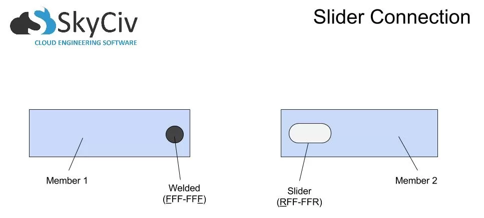
- Sliders – These occur when the connection between the joints is released in one of the three translational degrees of freedom. This allows the joint to move in the positive and negative directions in this degree of freedom while also rotating along another degree of freedom.
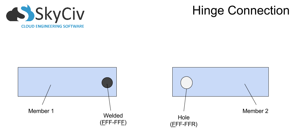
- Hinge – These occur when the connection between the two joints is fixed in all the translational degrees of freedom but is released in exactly one of the rotational degrees of freedom. The members are able to rotate about on another in one direction but remain fixed in place. This is most often seen in a pin connection situation.


Types of Supports
There are three main types of supports often encountered when modeling in SkyCiv (there are more than these three but these tend to be the most prevalent).
- Fixed Support – These occur when the connection between the member and the surface is fully rigid. All forces and moments from the end of the member pass fully into the support.
- Pinned Support – These occur when the connection between the member end and support is fixed in all the translational degrees of freedom but is released in exactly one of the rotational degrees of freedom. The members is thus able to rotate about the support along one axis but will remain fixed in place.
- Roller Support – These occur when the connection between the member and support is released in one of the three translational degrees of freedom. This allows the member to move along the positive and negative directions in this degree of freedom while also rotating along another degree of freedom.
- Bonus: Spring Supports are also possible to model using SkyCiv. Though they are outside the scope of this tutorial, you can learn more about them here.

FAQ
Yes, for certain scenarios, such as slabs on compressive soils, it may make more sense to use spring supports instead of defining fixed supports. You can learn more about how to employ these in your model by checking out this page in our documentation.
Yes! It is imperative that you don’t simply guess what the fixity code for connections or supports is and do your best to model them to match your real-life scenario. Slight deviations can have impacts that propagate throughout your entire model, making changes to the overall analysis. Thus, if you have any questions, it is best to reach out to a member of our team and we would be happy to help talk things through with you.
You can read more by checking out our dedicated documentation page at the following link.


