In this article, we will explore the difference between truss and frame members. This difference exists mainly due to the way they are connected to other members and it affects the structure's behavior in response to loadings. Often structural software like SkyCiv Structural 3D will have an option for selecting these types of member elements.
Frame Members
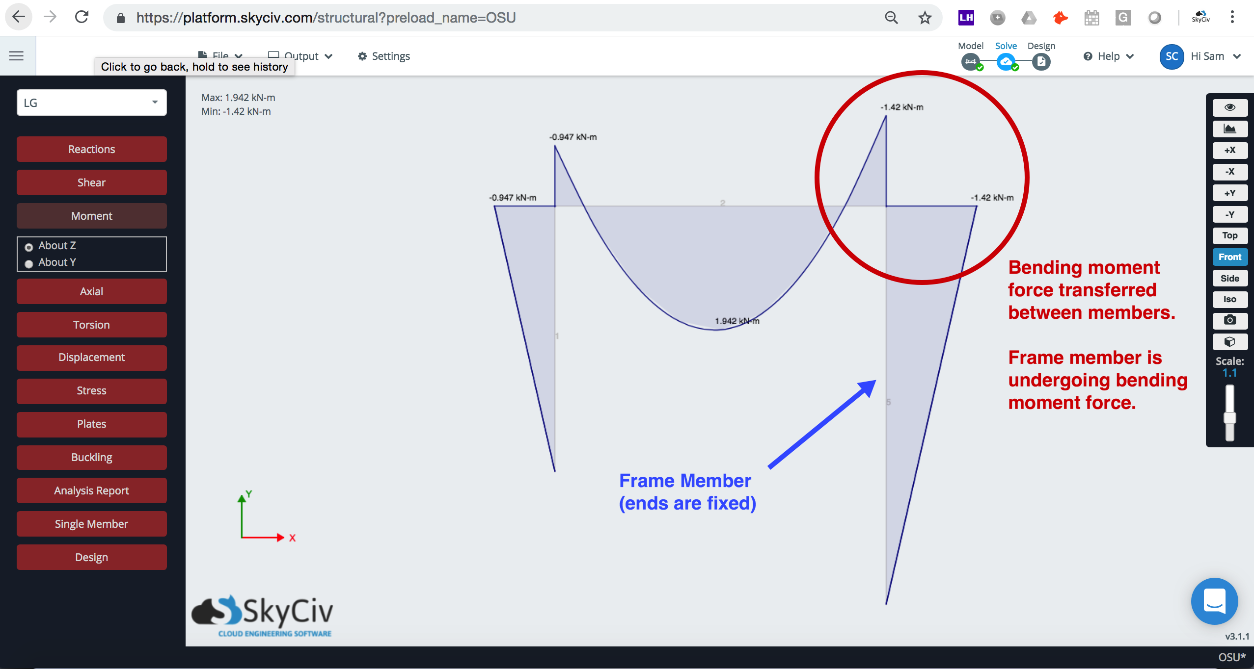
Frame members are like beams in that they are mainly designed to carry transverse loads along their length. These external loads cause internal forces like shear and bending moment. Some frame members (like columns) can even be designed to handle high axial (longitudinal) loads. These types of members carry these loads because of the way they are connected to each other or the rest of the structure. They are connected via fully rigid joints like welded or bolted connections which allow the transfer of shear and moment.
Truss Members
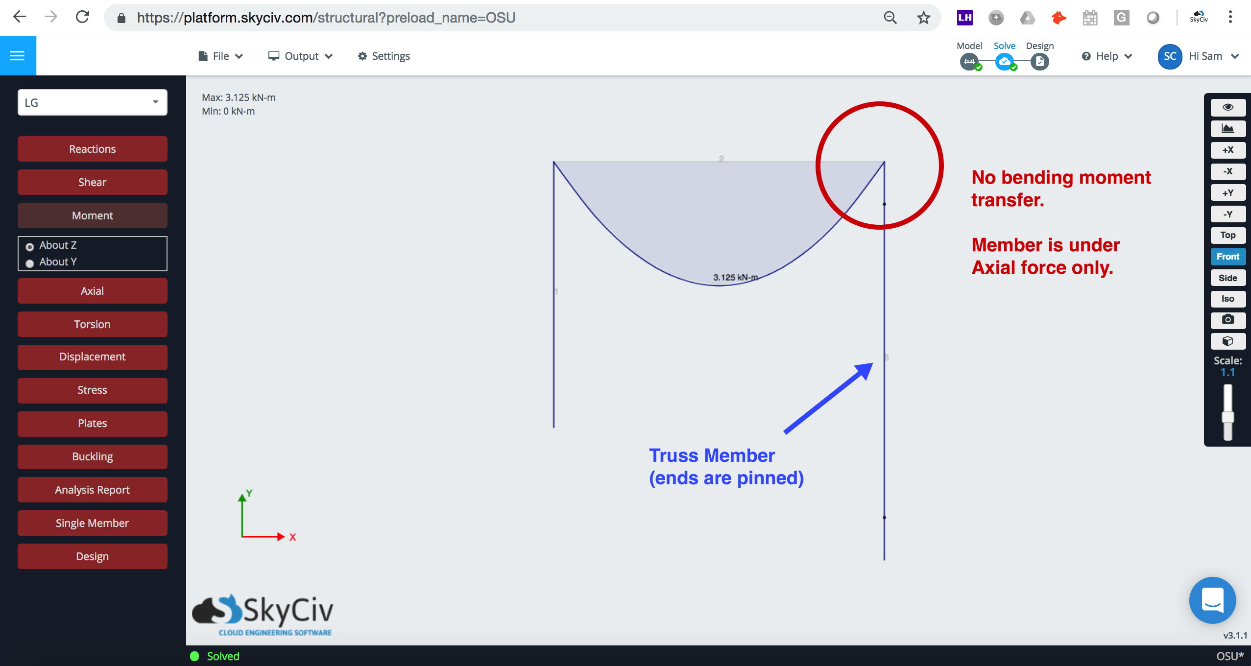
When I imagine truss members, I usually think of rods connected by pin joints. Truss members are free to rotate at their ends through the use of pin joints. This means that shear and bending moments are not transferred to the member. The only type of load that a truss can support are axial loads (tension and compression).
Because truss members are free to rotate, this implies that a structure made purely from truss members, like a space truss, must be triangular in nature. Otherwise, it would be unstable and collapse. Imagine a square structure of four truss members with freely-rotating joints; it would simply topple-over. Whereas as a triangle structure of three members made from pin joints would be stable because you cannot topple-over a triangle.
Try out our Free Trusses Calculator to find out what SkyCiv Structural 3D's truss analysis functions can do.
Difference between Truss and Frame: A Comparison Table
Below is a simple table comparing both types of members:
| Frame | Truss | |
|---|---|---|
| Joint | Rigid Joints at Ends | Pin Joints at Ends |
| Transverse Rotation | Fixed | Released |
| Internal Loads | Axial, Shear, Bending Moment, Torsion | Axial Only |
| External Loads | Axial, Transverse, Torsional Loads | Axial Loads Only |
| Software Fixity Code | FFFFFF | FFFFRR |
Truss and Frame Members in Software
Structural analysis software like SkyCiv Structural 3D can easily handle truss and frame members via the use of member-end fixities. Some software packages may refer to this property of the member as end releases because it controls how whether the member's degrees of freedom are Fixed (F) or Released (R).
On SkyCiv Software you will see that the truss member's rotation about its transverse axes can be released by the fixity code FFFFRR to simulate its end condition in which it is free to rotate. On the contrary a frame member's rotation is fully fixed so its member-end fixity code is FFFFFF. For more information about member-end fixities please consult our documentation for useful images and video tutorials.
Summary
In summary, a member is categorized as a truss and frame by the way it is connected at its ends which determines its ability to carry certain types of loads. Truss members are free to rotate and can only carry axial loads, whereas frame members are rigidly connected and can support all load types. When it comes to usage in structures, a truss member can afford to be lighter than frame members since it only carries axial loads. This light-weight nature of the member can come in handy with structures that span large distances.

CTO and Co-Founder of SkyCiv
BEng Mechanical (Hons1), BCom