How to Model and Analyze a Cable Lifting Structure
Learn how to perform a cable analysis on a structure with this simple tutorial. Looking at how to model the frame, apply loads to simulate equipment and other dead loads, before analysing the structure using SkyCiv’s FEA software.
The walkthrough will also look at common issues with solving cables.
Model your steel frame
Let’s start by building out a simple frame, this will be what we’re lifting using the cable elements. We’re going to make the most of the following handy modeling features:
- Pen Tool – model quickly using the pen tool
- Multi-edit – hold CTRL and drag the mouse to select and multi-edit parts of your model
- Search Sections – quick add sections from our library in seconds, using search
- Area Loads – one way, two way and wind load area loads that automatically calculate (and readjust!) the tributary areas of members.
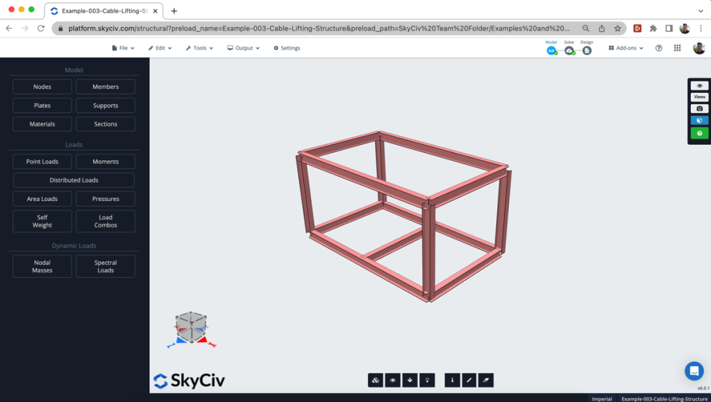
Adding your cable elements
So now we add the cables. Cables are non-linear elements, so are basically added the same way you would add any other member. The main difference is that cables are never in compression, have zero flexural, torsional or shear capacity (they are tension-only) and they often exhibit large displacements and non-linear behavior. So analysing these types of elements is treated slightly different to regular steel elements that have flexural and other strength.
Modeling the cable elements is done the same way you would any other element. However, when you are assigning the attributes, you would select Type: Cable. This will automatically assign the element with pinned end fixities and have it treated as a cable element in the solver.
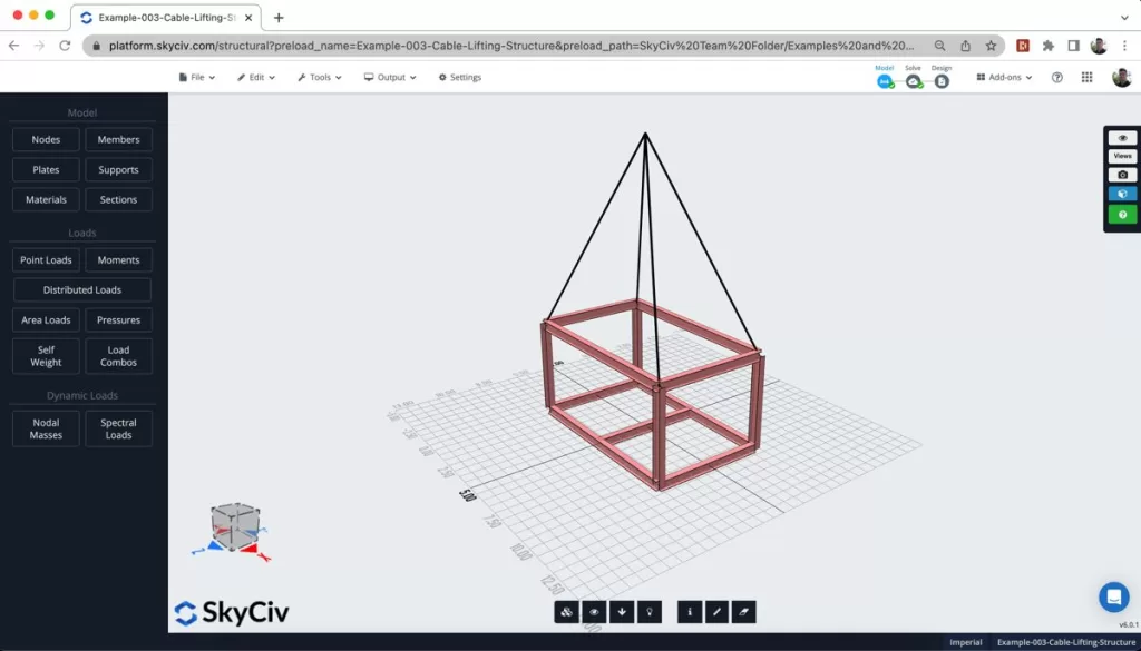
Opening up the Renderer view, clearly shows the cable elements (in this model, denoted as Section ID 2).
Applying equipment and other loads
Applying equipment loads to your frame structure is the same as in regular analysis models. In this case we have applied an equipment load (using two-way area loads) and some other dead load (using one-way area loads).
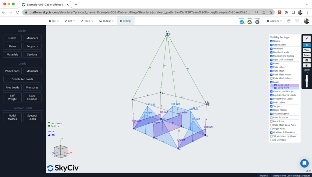
Performing a non-linear analysis and repairing stability issues
Cables typically undergo large deformations when subjected to significant loads. Geometric nonlinearity accounts for the changes in cable geometry as it deforms. The initial assumption of linearity in the cable’s response (as in linear static analysis) becomes invalid when the deformations become significant.
It is necessary to use a non-linear analysis when cable elements are present, since non-linear analysis considers these geometric changes and provides more accurate results. When you load or tension a cable, after each step the structure has moved so much that the loads are not necessarily being applied in the same position as before.
Therefore, for this structure we will need to perform a non-linear analysis. Note: if user selects Linear Static Analysis, it will automatically revery to non-linear analysis.

Reviewing the results
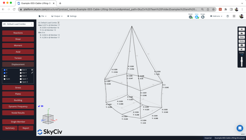
Once the analysis is successfully completed, it’s a good idea to check the deflections to (a) ensure the numbers are reasonable and (b) animate the deflection of the structure to see if it deforms in a way you’d expect. If cable elements are not solving correctly, you will see jagged deflection curves and could be an indication that the cables are under or overloaded.
A well behaving cable element should be smooth, sagging and showing tension-only deformations, as seen in the example model:
Another result worth reviewing, is the axial stress in the cable tendons. Obviously, since the cable has no shear or flexural capacity, all of the force is transferred via tension in the element. By default the structure will highlight any stresses that exceed the material yield/ultimate strength. You can also enter in your own custom allowable stress, so that you can easily identify elements that exceed your stress limits:
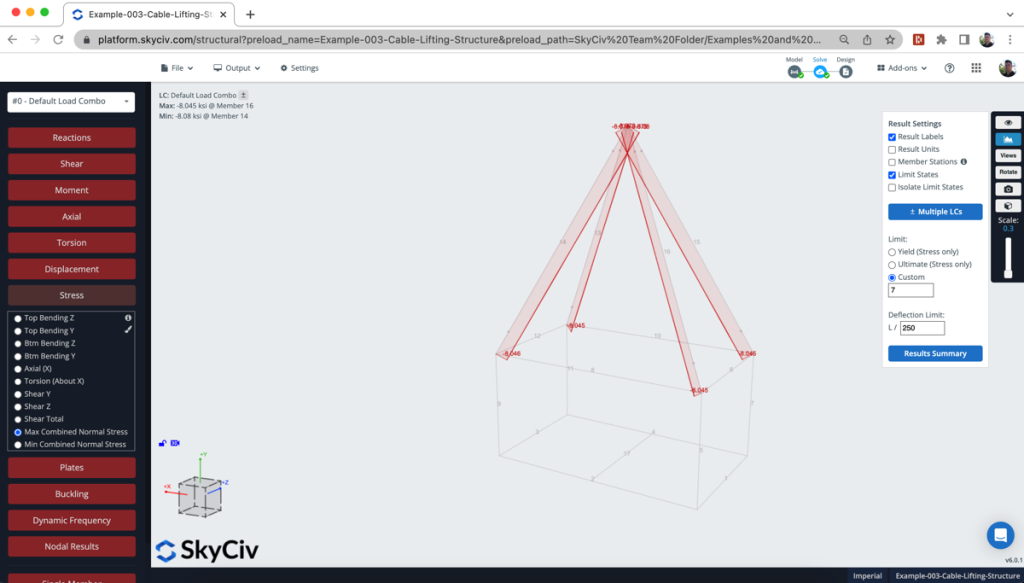
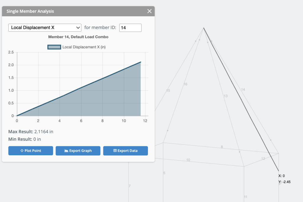
Another result worth considering is the elongation in your cable. Similar to the deformation result previously reviewed, however in this case we are looking at how far the cable has stretched. There are often limits to what is acceptable when it comes to designing cables. Displacement analysis helps in evaluating the cable’s behavior under different load conditions and ensures that the displacements are within permissible limits.
For this, we can use the single member analysis and toggle on Local Displacement X which will give us the total deflection in the cable along its own axis. In the below example, the cable is elongated by 2.1164 inches:
Common solving issues in cable analysis
If your cable structure is failing to solve (a lot of times due to instability or the inability to converge), here are some common things to check or try:
- Check diameter size
- Check Cables are Not Over/Under Loaded
- Reduce your Convergence Accuracy
- Add Extra Supports
- Check Your Other Members
FAQ
Cable sag is accounted for by considering the cable’s self-weight and the applied loads, which cause deflection. Engineers typically use catenary equations or numerical methods to determine the cable’s shape and sag under specific loading conditions.
Yes, you can apply a prestress load to a cable element
Yes, however the software will automatically handle this for you. In other software, the cable element may be broken into smaller elements, which can be cumbersome to adjust. SkyCIv will retain the element as a single member, and only split the element on the solver side – making modeling and changes easier.


