Any connection that has the capacity to transfer moment between the structural members (two or more) is defined as moment connection. This term is commonly used in steel structures as opposed to shear connections that are able to transfer only shear force between the bridging members. As moment connections can transfer moment between the child members, the relative rotation is restricted, which is not the case for shear connections. Of course the actual rotation restriction offered by moment connections depends upon the actual rigidity of the connection that in turn depends on its detailing (e.g. number and layout of bolts, welding thickness and layout).
It should be mentioned that the dimensions of any connections are dictated by the relevant dimensions of the bridging structural members. For instance Reinforced Concrete (RC) connections in buildings are typically able to transfer both moment and shear since the members are monolithic. On the other hand, as steel column members have often H-type or Square hollow cross section and beams have I-type cross section the connection type depends upon the structural engineer as the member flanges provide the moment resistance and the web provides the shear resistance. This article focuses on steel moment connections.
When should moment connections be used?
Moment connections are used in cases where beam or column splicing in zones with non-zero bending moment is necessary or in cases high degree of structural indeterminacy is desired. For instance, steel frames rigidly connected at the base present higher stiffness and strength than pin-supported frames and are therefore subjected to much lower deflections at the serviceability limit state. Moment connection detailing entails additional erection cost compared to shear connections. In the global scale though, the choice of moment connections may lead to reduced needs in terms of bracing member sections that provide resistance to wind or earthquake forces, which can increase material savings. The following figure shows the bending diagram of a simple frame subjected to a vertical uniform load of 50kN/m using SkyCiv Structural 3D. The beam-column connections must be designed to resist the moment from analysis while the column-foundation connection must only guarantee the transfer of vertical loads (pinned connection).
Figure 1: Bending moment diagram of steel frame pinned at the base under uniform vertical loading of 50kN/m.
How are moment connections performed?
The detailing of moment connections is performed using either bolts or weldings. Bolted moment connections can be created using beam endplates (which might be extended or not) combined with bolts working mainly under tension/compression. Moreover, L-shaped plates can be fixed to the flanges of the child members using bolts that must be designed to take the shear force generated by the tension/compression forces in the flanges. Welded moment connections are performed using partial of full penetration butt welds which offer high rigidity but need careful inspection. For this reason welded connections are most times constructed in the factory.
Unlock your Free Account
Register for a free account and get access to powerful analysis + design software:
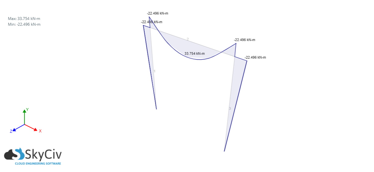 Figure 1: Bending moment diagram of steel frame pinned at the base under uniform vertical loading of 50kN/m.