Lateral deflection is something that every engineer must take into account when analyzing their structure. Whether that is for serviceability or strength requirements, lateral displacement can become a very important failure method to consider. Their lateral deflections most commonly come from wind and seismic forces.
When looking at the larger context of a structure, this lateral deflection goes beyond individual structural elements and is called drift.
What is Story Displacement?
To understand story drift, also known as inter-story drift, we first need to understand story displacement. Story displacement is the deflection of a single story relative to the base or ground level of the structure. Intuitively, we can expect higher total displacement values as we move up the structure. So, a graph showing the story displacement vs. the height of the structure looks exactly like the deflected shape.
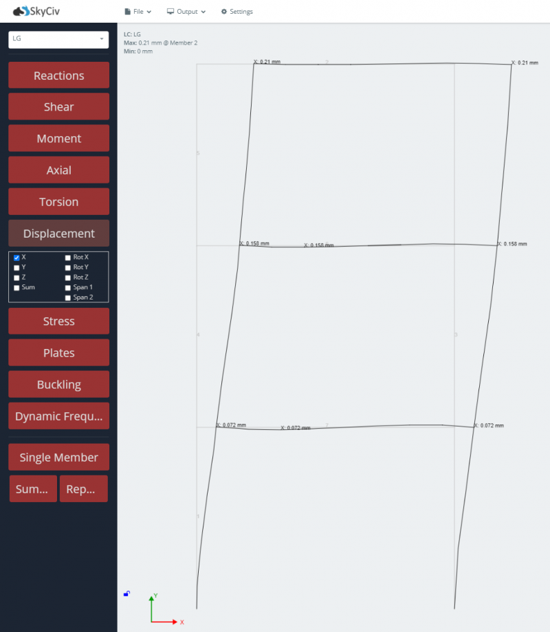
In SkyCiv Structural 3D, these values are shown as the X, Y, or Z-axis displacements, depending on which directions are lateral for that specific structure. Story displacement is very easy to find using Structural 3D because users can always view their structures displacement values after analysis:

Figure 1: SkyCiv Structural 3D model showing the total story displacement of a frame at each level
In the above image, we can view the nodes on the outside of the structure and determine our X and Z-axis lateral story displacement.
What is Story Drift?
Story drift then is the deflection of a single story relative to the previous story. Because the story drift is relative to the nearby levels, we can expect a different looking graph when comparing story drift to the height of the structure.
How is it calculated?
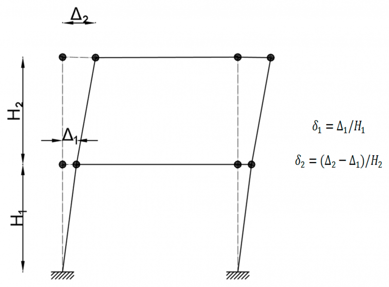
The calculation of story drift is very simple, given the story displacements from structural analysis. In general, to find the story drift of level "X", you would take the story displacement of level "X", and subtract it from the story displacement of level "X-1". For example, the story drift of level 4 is equal to the total story displacement of level 4 minus the story displacement of level 3.
Story drift is sometimes shown as a ratio, where the story drift value is divided by the story height. The figure below represents this with the (δ) character.

Figure 2: Depiction of story drift (mdpi.com)
Specifically for seismic drift, there are additional provisions based on which code you are using, so when considering story drift in this case, make sure to review the relevant code documents governing your project.
Story Drift Limits
When it comes to the limits and allowable story drift, it depends on what kind of force is causing the deflection, with more rigorous limits set for seismic forces. These limits are usually presented either as a ratio or a percentage, but always depend on the story height, usually represented as "h" or "H"
For wind loads, ASCE 7 does not impose an allowable drift limit, but there are common practices and commentary on what engineers should consider. Looking at Appendix CC of ASCE 7, common values of inter-story drift range from H/200 to H/600, with the most common limit used being H/400.
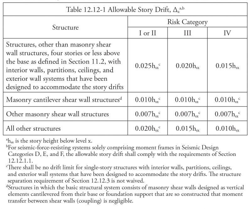
For seismic loads, the limits range depending on the code and country but are usually given directly in the code. Once an engineer has the story drift calculated using the elastic displacement results and the special provisions for seismic forces, the allowable drift limits can be examined. Specifically for ASCE 7, they are shown as a product of the story height "h" and a constant, specifically:

Figure 3: Allowable Story Drift according to ACSE 7-16 Table 12.12-1
Make sure to consult all relevant building code documents in your area when considering lateral story displacement and drift.
Sources
[1] Al-sheikh, Abdulqader. “ASCE 7-16 Provisions for Lateral Drift Determination.” STRUCTURE Magazine, www.structuremag.org/?p=15358.
[2] “Difference between Storey DRIFT & Storey Displacement.” YouTube, YouTube, 18 May 2019, www.youtube.com/watch?v=ijgyDoKXllE.


