Beam with Web-Opening Design
This tutorial helps walk you through the basics of using Beam Shell FEA to model a basic beam with holes in its web. This video will take you from a beginner to being able to model your own designs independently. If you are looking to use SkyCiv to model tapered beams, this is the best place to start!
Introduction
This tutorial will walk you through how to design a beam with web openings using SkyCiv Beam Shell FEA. We will cover how to model a beam using the Beam Shell FEA module, modify the web, flanges, and stiffeners of the beam, and eventually add the openings as well.
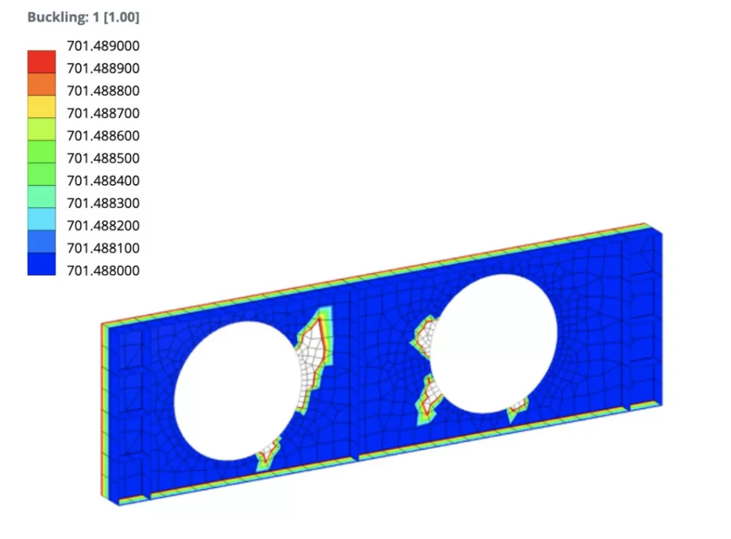
Modeling – Web
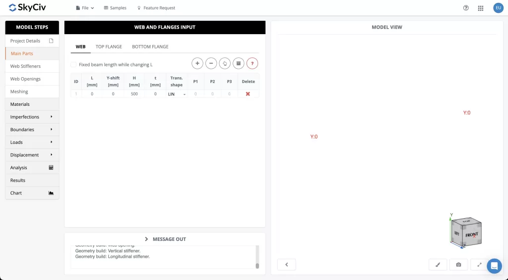
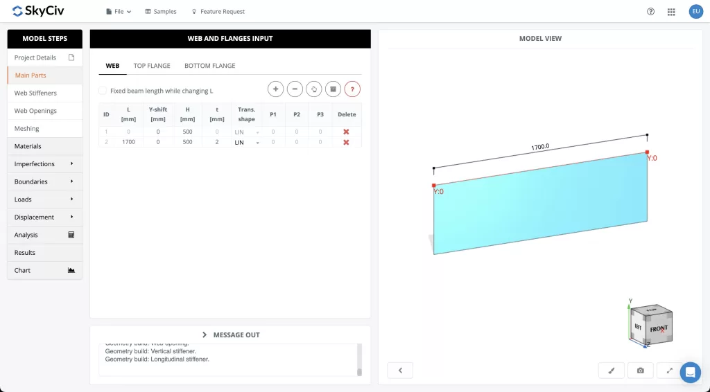
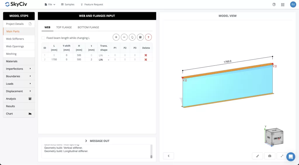
The first step in modeling your beam is defining the web shape of your section. Select the “Main Parts” tab in the side menu and then input desired values for the length, height, and thickness of the web. More information is available in the SkyCiv Documentation site which covers what all the variables are. You can make your design as refined as possible, but this tutorial will cover a basic web using simply thickness (t), height (H), and length (L).
After you’ve defined your web, it is time to move on to designing the flanges.
Modeling – Top & Bottom Flanges
The flanges are defined very similarly to the web with length (L), width (b) and thickness (t) being the main variables that must be defined. The top and bottom flanges are defined separate and thus one can layout a design with the bottom or top flange equal or even slightly larger or smaller depending on anticipated loading and design requirements.
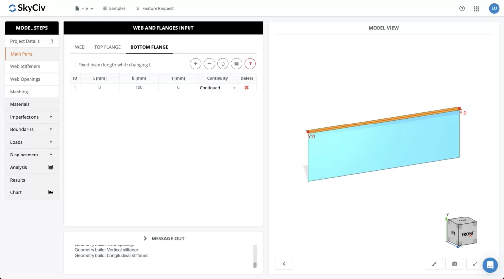
Once the flanges have been defined, it is time to move onto adding stiffners to the member.
Modeling – Vertical & Longitudinal Stiffeners
Stiffeners can be added in both the vertical as well as horizontal directions. For both horizontal and vertical stiffeners, the required thickness, location, and length of the stiffeners must be defined.
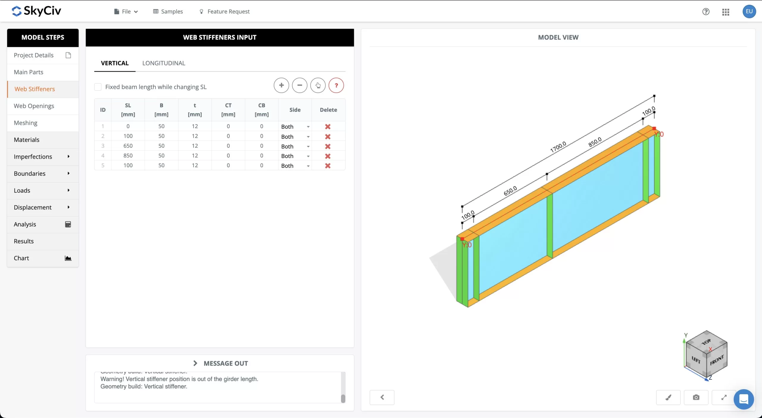
When laying out the stiffeners, attention should be paid to where the loss of strength is anticipated to occur due to the holes that will occur in the web.
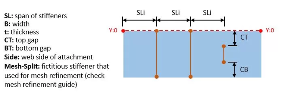
After the stiffeners have successfully been added in the vertical and longitudinal directions, it is time to move on to adding the holes in the web.
Modeling – Adding Web Openings
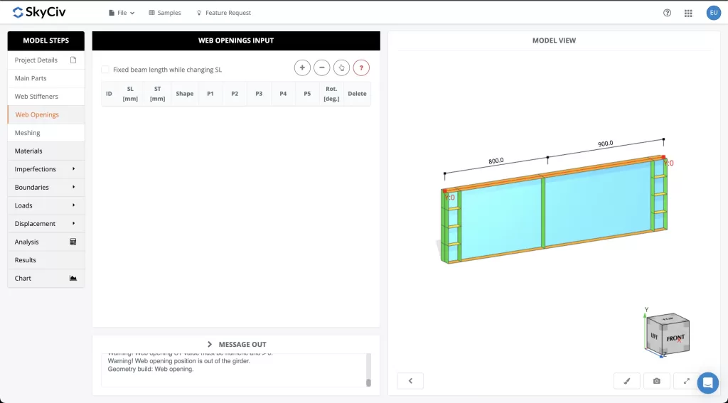
The web openings are defined similarly to the other elements with the starting span from the left (SL), and span from the top (ST) working to define the position of the web in reference to the web. Additionally, one is able to input not just circles but rectangular and polygonal openings as well. Finally, the rototational angle of the opening with relation to the web can be defined as well.
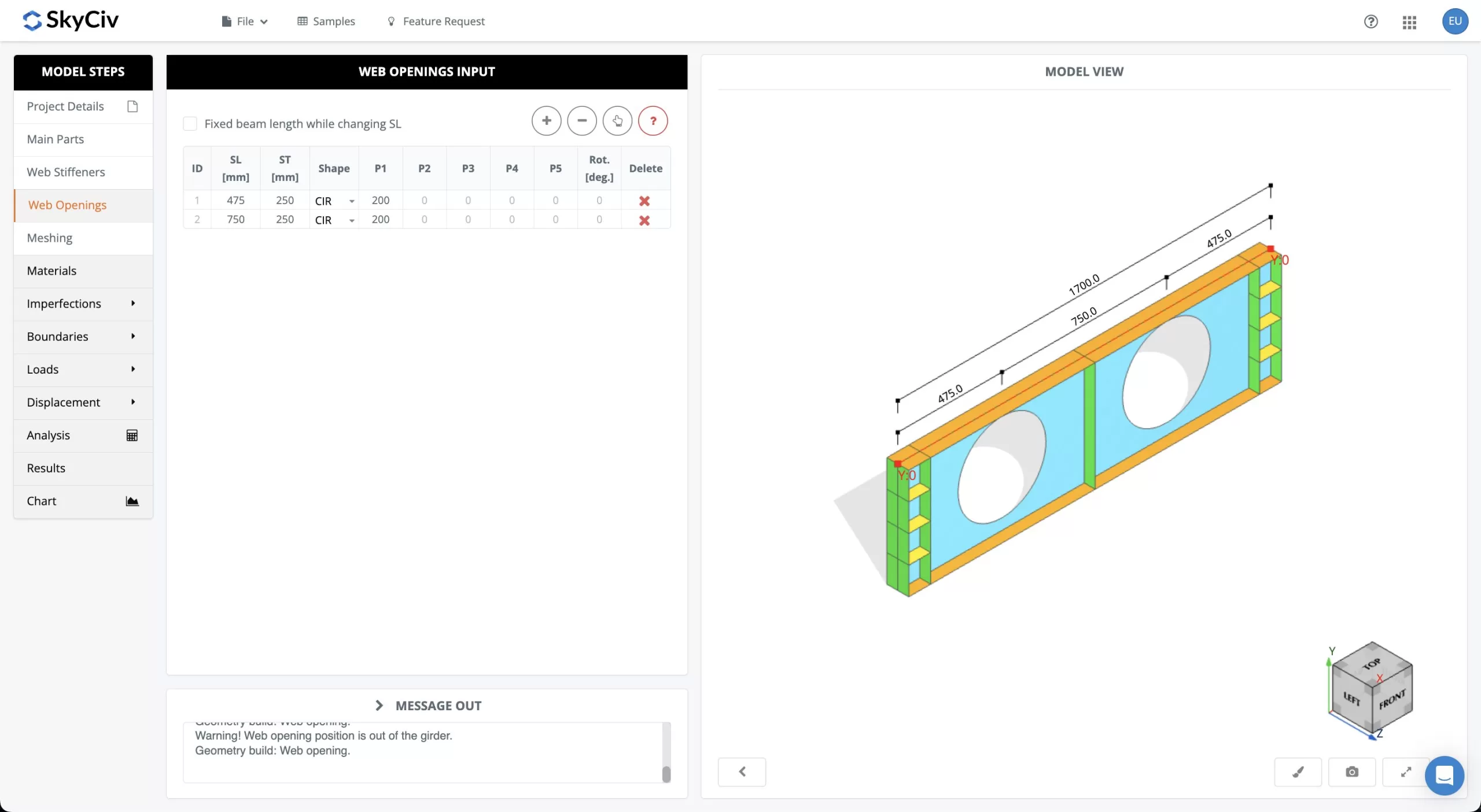
After the desired holes in the web have been defined, you are ready to move onto the final steps of your design.
Modeling – Meshing, Boundaries, & Adding Loads
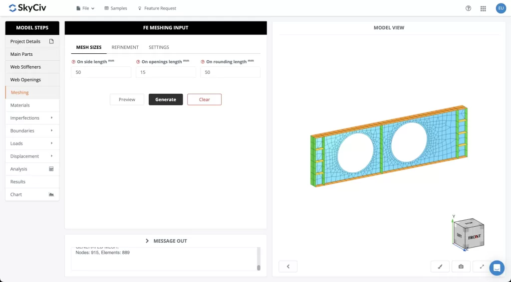
Now that your member has been created and the holes defined, you can move onto the “Meshing” tab on the left sidebar. From here, you can define how small you would like the mesh sizes. The smaller the mesh sizes the more accurate the analysis will be but the analysis will also take a bit longer to load as well.
The next step is defining how you would like your support interaction to be modeled. Under the “Boundaries” tab, you can add fixity conditions for at relevant points to restrict any boundary conditions at the points along your beam you would like.

After you are done setting the parameters hit “Generate” and your member will be meshed making it ready to add loads and analyze.
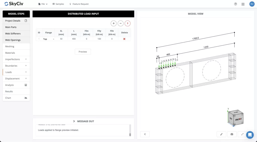
Once the member has been meshed, you can add loads under the “Loads” tab. You can define the self-weight of the member, add Area Loads, and choose whether the load will be directed along the flanges or stiffener edge.
Once you finish laying out the loads you would like to analyze, move onto the “Analysis” tab.
Analyzing Results
The SkyCiv Documentation site goes into detail about the various Analyses Types offered by the Beam Shell FEA module. For this particular example, we will be performing a Linear Buckling analysis though there is flexibility to analyze what you are specifically looking in your own designs.
Once you are comfortable with the analysis input values, select the “Perform Analysis” button and an analysis will run.
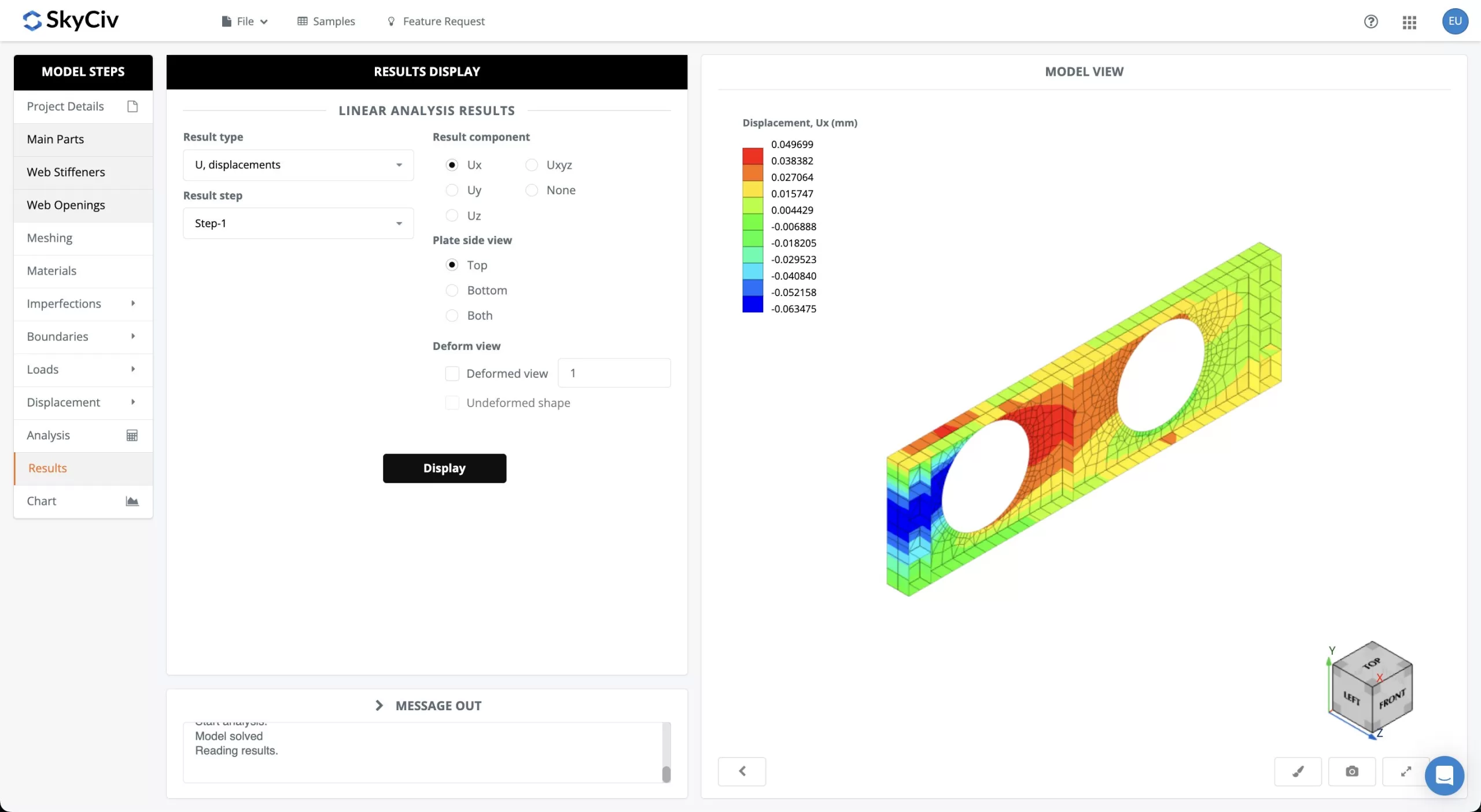
From the “Results” tab, you can analyze your results and if you would like to run another analysis you can always move back to the “Analysis” tab to setup and evaluate another analysis.
Conclusion
You have now successfully completed your own example of designing a beam member with openings! With the techniques shared here, you should be able to undertake your own analyses using Beam Shell FEA now and designing your own custom members.
FAQ
Yes, Beam Shell FEA is a separate module but it is fully integrated with SkyCiv S3D. You can begin your designs in S3D or our Free Beam Calculator and continue your FEA analysis in Beam Shell FEA. Your purchase of a professional plan includes the full use of Beam Shell FEA.
You can view our pricing for a monthly subscription here.
Yes, you can learn more about our Beam Shell FEA at its page on SkyCiv’s documentation site.
Additionally, you can read about the specifics of each type of analysis the Beam Shell FEA module conducts there as well.


