Introduction
In the following tutorial, we will learn how to design a concrete element using the Standalone RC Design Module. We will define members, rebar layouts, forces, check reports and optimize our elements.
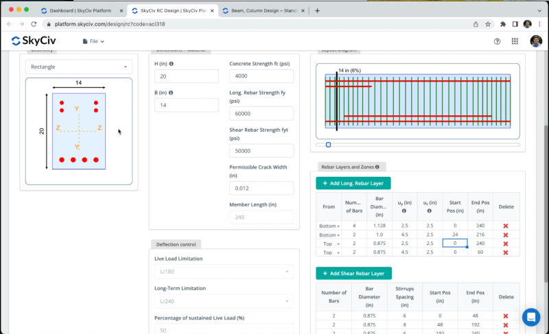
You have to open the RC Design Module from your SkyCiv dashboard and create a new project using the design code: ACI 318-19.
Members
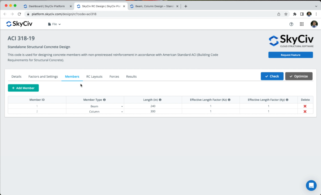
To create concrete elements, we need to go to Members, in that section we can add Beam / Columns for our design, for the purpose of this tutorial, we will use the two elements created by default. We can modify the length and effective length factors if needed.
RC Layouts
We can define a geometry for each of our members, in the case of beams we can select:
- Rectangle
- Tee shape
In the case of columns, we can choose between:
- Rectangle
- Solid Round
We can also define the dimensions for the members, the beam will have a height = 14 in, Width = 20 in, we will use the material properties obtained by default.
To create rebar layouts we can click on Add Long. Rebar Later or Add Shear Rebar Layer, we will add a top rebar layer at the ends of the beam as shown in the following image:
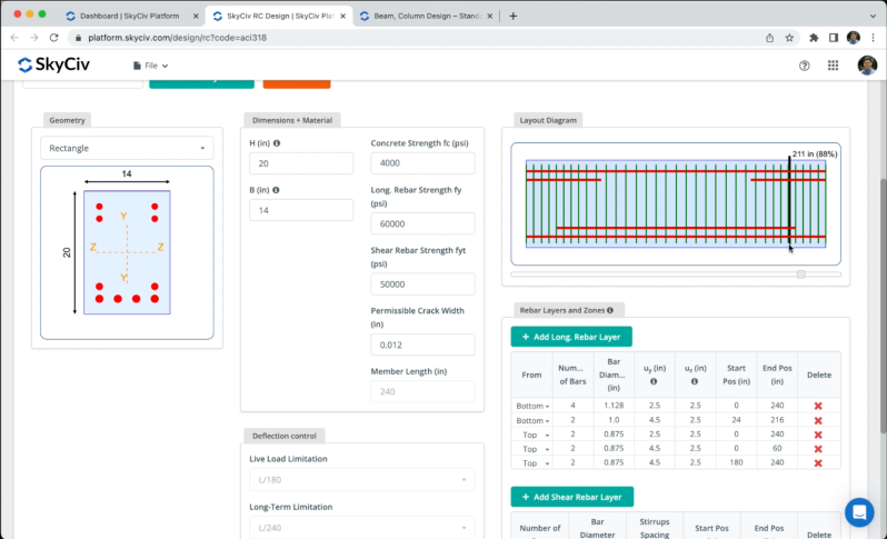
After we complete the layouts, we need to click on Save Layouts.
Forces
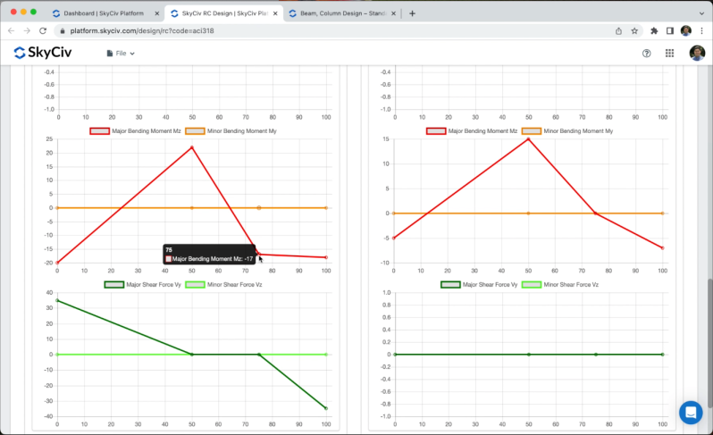
We can define forces for each of our members ( Ultimate Limit State Forces and Serviceability Limit State Forces ) we can achieve this by clicking on Add Check Point to put the desired forces as shown in the image.
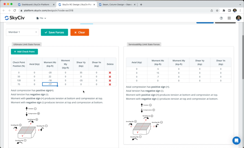
After we defined the forces we can go to the graphs to check the Axial, Moments, and Shear diagrams.
Results
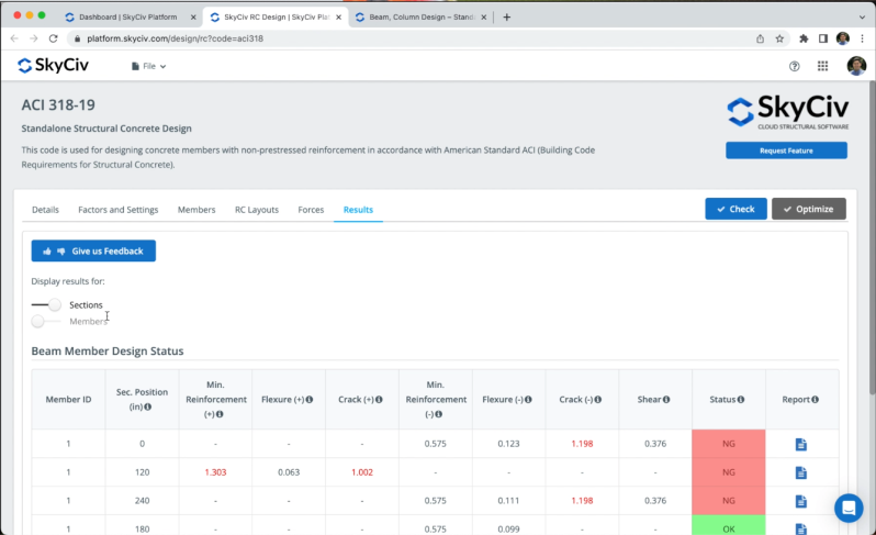
After we defined our members and forces, go to Results > Check to obtain the design checks, we will see results for Sections and Members. The sections will show the results for all the sections which correspond to the Check Points defined in the previous chapter. If we select the member’s results, the software will use the worst cases of the section analysis to represent results for each member.
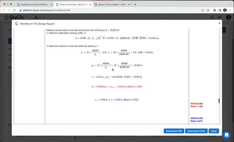
We can open the reports to see all the calculations and validations for each section, we will see step by step all the hand calculations and the status for each verification.
Optimization
We can optimize the sections reinforcement by clicking on Optimize. We could modify the predefined values, however, for this example we will use the values by default as shown in the image.
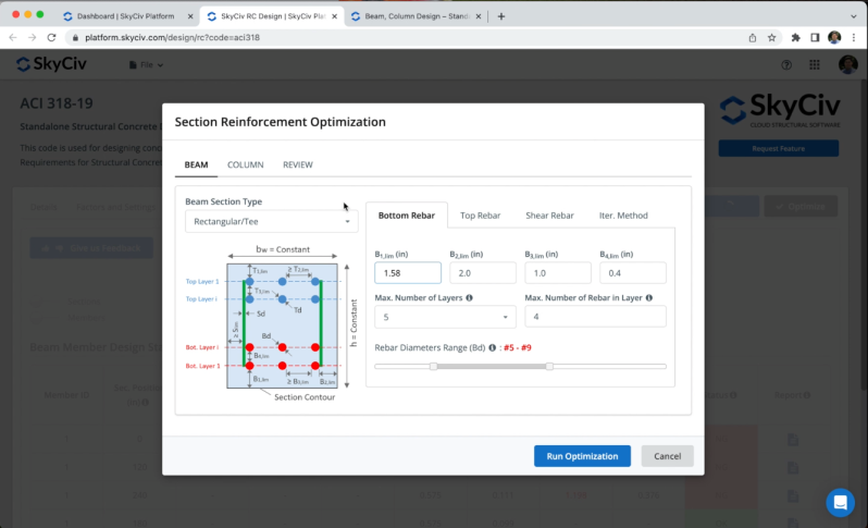
After we obtain the optimized reinforcement, we can click on OK to see all the results and calculations for our new optimized reinforcement.
FAQ
Yes, you can refer to the following article Beam, Column Design – S3D
After you run the Check, you can open the report for the column section and you’ll find the interaction diagram.
Directly on RC design, you can’t design plates, however, we have another module called Plate Design Module that is fully integrated with Structural 3D to design your plates.


