Designing Custom Concrete Sections in SkyCiv
Learn how to model, analyse and complete basic design checks on a custom concrete section using Structural 3D, Section Builder and the SkyCiv General Section Designer.
In the tutorial, we will work through an example problem where we are given a concrete column with a custom section and need to complete design checks on it.
Introduction
In the following tutorial, we will explore how to model, analyse and design custom concrete sections using the SkyCiv Section Designer. In the tutorial, we will be checking a concrete column with a custom section.
This tutorial includes a step-by-step guide on:
- Modelling a column in Structural 3D (S3D),
- Assigning loads and load combinations to the model,
- Creating a custom section,
- Applying section reduction multipliers,
- Solving the model and viewing results
- Complete section design checks using the General Section Designer (GSD)
The Problem
We have been given the following problem to solve for this example:
An 18′ tall concrete column with a custom cross section is subjected to the following loads:
- A permanent compression load of 150 kip
- A lateral load of 10 kip along the X-axis and -24 kip along the Z-axis
The column is a cantilever, with a fixed base and the loads are applied at the top of the column.
Check the column for deflection (Height / 200) and complete a section check on the base of the column.
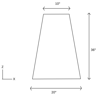
The column is to be checked with the following section dimension:
Modelling the Concrete Column
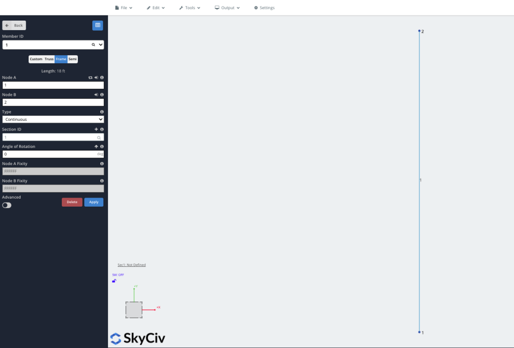
We will be modelling the column using S3D. From the SkyCiv dashboard, launch a new file of S3D and make sure your unit system is set to imperial (Settings > Units > Unit System = “Imperial“). The first step will be to define the nodes for the column. To create the nodes go to the Nodes menu. From this menu, we can input the X, Y and Z coordinates for each node individually, clicking Apply for each node to add them into the model.
Nodes will be applied at the following coordinates (X, Y, Z):
- 0, 0, 0
- 0, 18, 0
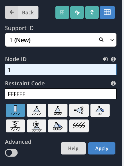
Next we can set the column supports. The column has been specified as a cantilever, with a fixed support at the base of the column. We can apply this by going to the Supports and enter the Node ID to be 1. We will keep the default restraint code of FFFFFF to represent a fully fixed support. Click Apply to add the support to the model.
Assigning Loads and Load Combinations
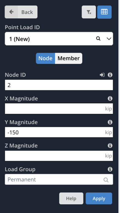
Next, we will assign loads to our model. We have been given a few loads to apply to the top of the column. Go to the Point Loads menu and input 2 in the Node ID input box. Our first load to apply is a permanent compression load. Enter a value of -150 kip in the Y Magnitude input box. We will also rename the load to be “Permanent” in the Load Group input box to denote that this is a permanent load. Click Apply to apply the load.
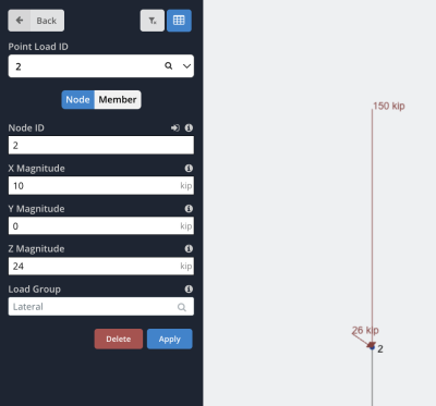
We will also apply a lateral load to the module. Still in the Point Loads menu, again, set the Node ID to be 2. This time set the X Magnitude to be 10 kip and the Z Magnitude to be 24 kip. Set the Load Group name to be “Lateral” and hit Apply. Your model should now show two individual point loads in the model, one with the compression load of 150 kip and another with the resultant lateral load of 26 kip.
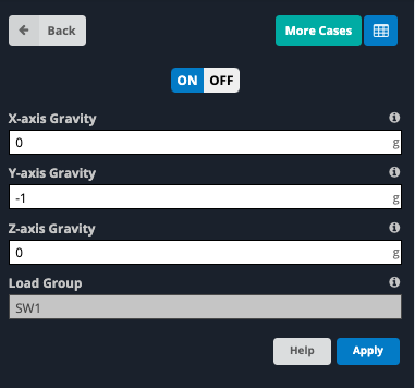
We will also assign a gravity load to the model to account for the self-weight of the column. Go to the Self Weight menu and select On to enable self-weight in the model. By default, this will apply a -1 g (9.81 m/s2) self-weight in the y-direction across the entire model.
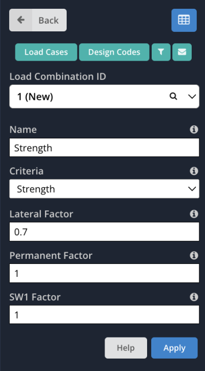
With loads applied to the model, the next step is to define load combinations. Go to the Load Combos menu. In this example we will define two load combinations, one for strength and one for serviceability. For the strength case, enter the following data into the input boxes:
- Name: Strength
- Criteria: Strength
- Lateral Factor: 1
- Permanent Factor: 1.2
- SW1 Factor: 1.2
Click Apply to add the load combination. For the serviceability case, input the following data into the input boxes and select Apply:
- Name: Deflections
- Criteria: Serviceability
- Lateral Factor: 0.7
- Permanent Factor: 1
- SW1 Factor: 1
Create A Custom Section
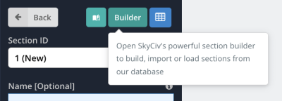
Next we can define the custom section for the column. We will be using the Section Builder to create a custom shape for the section. To access the Section Builder in S3D, got to the Sections menu and click the green Builder button at the top of the menu.
The section builder will open. As our shape is not a standard template available in the section builder, we will need to create a custom shape. In the menu on the left side of the screen, select Custom Shapes > Add Points Shape. A default shape with 6 points will appear. The coordinates for the points in the shape can be modified by going to the Dimensions tab in the menu on the right side of the screen. Based on the section dimensions provided above, we will assign the following four coordinates (Z, Y) with the Radius set to 0 for each coordinate.
- (0 , 0)
- (5, 36)
- (15, 36)
- (20, 0)
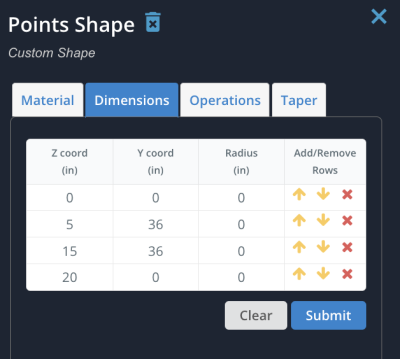
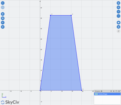
When we have set the coordinates, click Apply to make the changes. The section should now look like this:
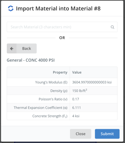
We also need to assign a material to the section. Still in the Section Builder, in the menu on the right side of the screen select the Material tab and select the Add From Database button. This will open a window where we can select from a database of standard materials. For this example, we will be using 4000 PSI concrete, which can be selected from the drop downs with the following selections: Imperial > Concrete > General > CONC 4000 PSI. Click Submit to apply this material to the section.
With the section material applied, we can now save our section to be used in the model. In the Section Builder, click Submit to save the section and return back to S3D. The section will automatically apply to the column as it is our first section in the model. We can review the column in the 3D renderer to check that it looks correct by clicking the Cube icon on the right side controls.
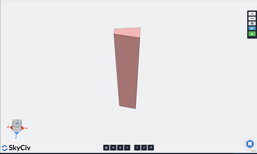
From reviewing the 3D view, we can actually see that our section is currently rotated incorrectly. The column taper should be parallel to the Z axis as per the section dimension drawing. If we leave this as is, our loads will be incorrectly applied along the column, so we need to rotate the column. To fix this, We can then select the member in the model to bring up the member properties menu on the left side of the screen. Set the member Angle of Rotation to be -90 degrees and click Apply. Your member should reorientate to the correct direction per below:
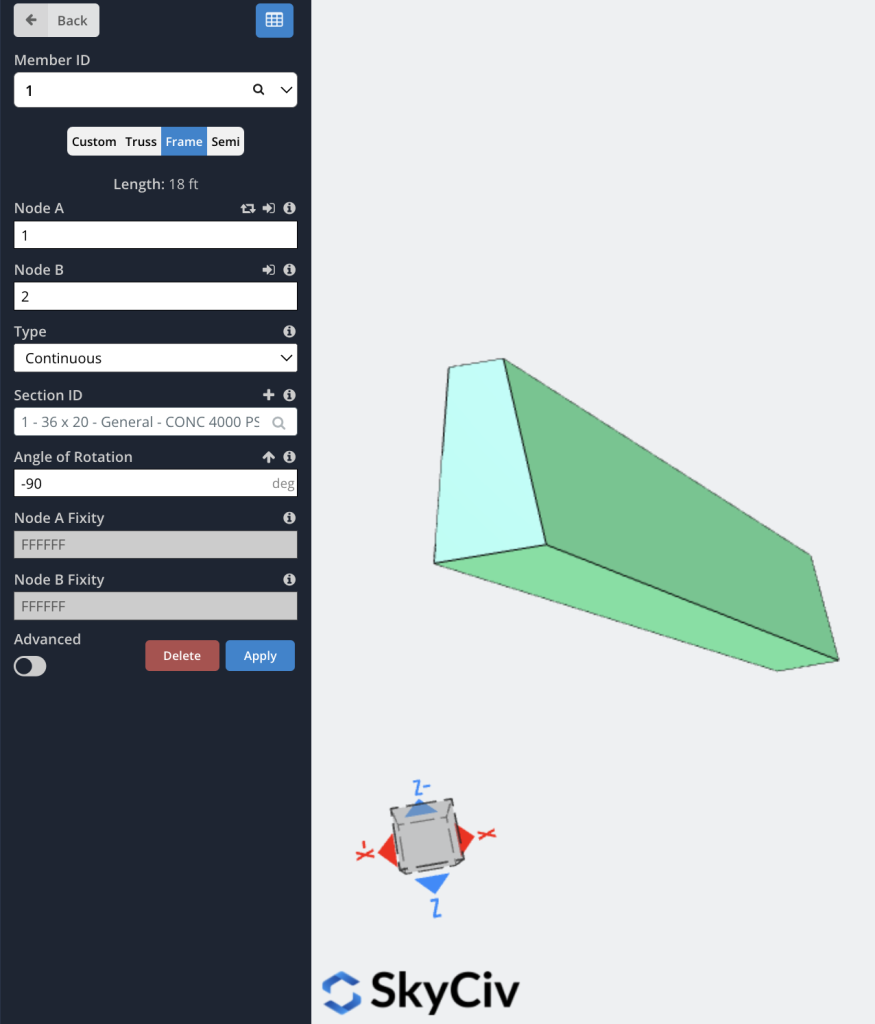
Now that we can see that the column is orientated correctly, we can exit the 3D renderer (click the Cube symbol again).
Applying Section Reduction Multipliers
Depending on what you are analysing and your specific design code requirements, you may need to apply section reduction factors. These can be important for concrete sections where a reduction in values may occur due to the loading of the structure, for example, you may want to account for a reduction in section stiffness due to cracking in a concrete section.
This can be done in SkyCiv by applying section reduction factors. These parameters can be accessed by hovering over Edit > Members > Section Reduction Factors. In this example, we will reduce the Moment of Inertia by a factor of 0.7 for both the Iz and Iy. For simplicity, we will leave the other parameters set to the default of 1, which means the software will use the gross section properties for these parameters. Click save to make apply the changes to the section.

Solving The Model And Viewing Results
We have now finished modelling our column and are ready to run the analysis. For this particular model, we will be running a Non-Linear Static Analysis. From S3D, hover over the Solve button in the top right corner and select Non-Linear Static + P-Delta.

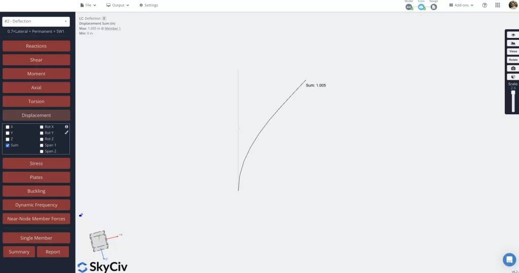
The analysis will run and we will then be able to view the results of the analysis. S3D allows you to review a range of different results including displacements, reactions, shear forces, moments and many more. One of the required checks for our problem is to assess the deflection against a deflection limit of Height / 200. Noting that our column is 18 feet tall (216 inches), our deflection limit will be:
216 / 200 = 1.08 inches.
When reviewing the deflections of the column, we want to make sure we are viewing the correct load combinations. We will need to switch the load combination to be “Deflection” load combination that we defined earlier. We can select this from the drop down at the top of the menu on the left side of the screen.

We can then check the deflections for this selected case. Click the Displacement button in the left menu to expand the options for displaying displacement values and tick Displacement Sum (untick all other options). The sum of all displacements will then display. As we can see, the sum of displacement of the column is 1.005 inches which is less than our limit of 1.08 inches so therefore, our column has satisfied the deflection check.
Complete Section Design Checks
With the deflection check complete and satisfied, we will now move on to check the base section of the column for strength. SkyCiv makes this easy through the use of the General Section Designer (GSD). We want to complete the checks using the Strength load combination. Select the strength load combination from the drop down to switch to this combination. We can then access the GSD directly from the results window by Right Clicking the column and selecting Launch Section Designer (GSD). A second window will pop us asking us to specify the member ID to be used in the GSD. Leave this set to 1 and click Launch GSD.
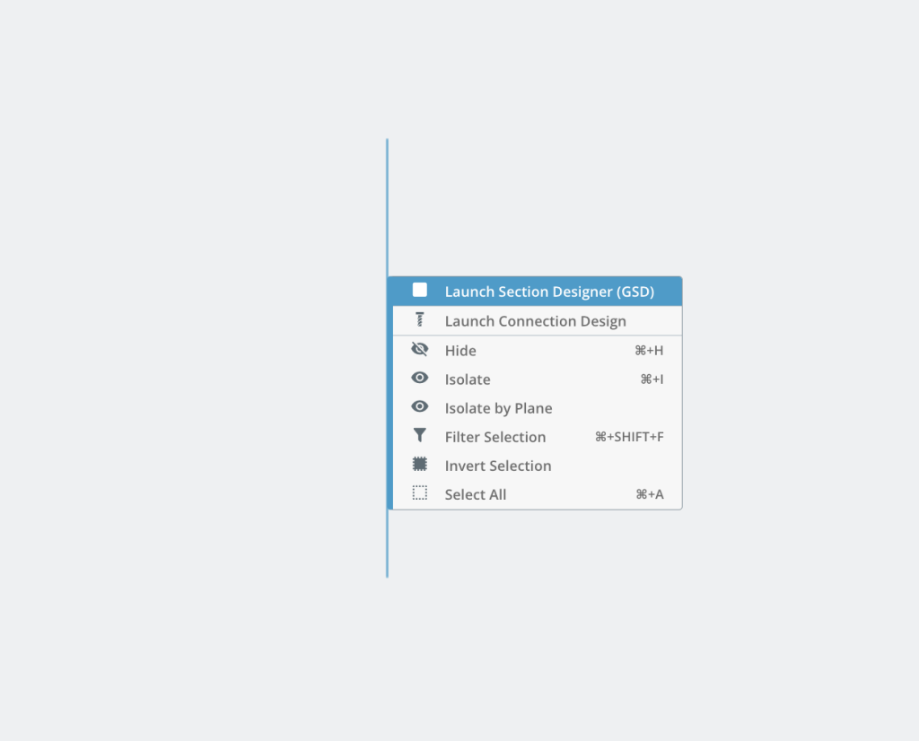
The GSD will launch in the Section Builder. The GSD is controlled by the menu on the right side of the screen. There are a few menus to step through before we can run the section check.
Concrete Material Menu
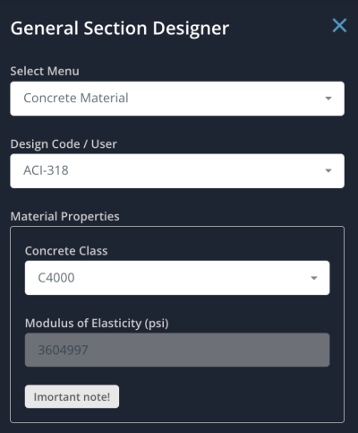
In this menu, the concrete properties of the section are defined. The Design Code / User dropdown allows users to have option to choose a particular design code to be used for selection of the concrete properties. For this example, we will be basing the design on ACI-318. Select this from the design code options. This will then update the options available to be chosen in the Concrete Class input. As noted earlier, the design is based on a 4000 PSI concrete, therefore we will select C4000 for the concrete class.
Rebar Material Menu
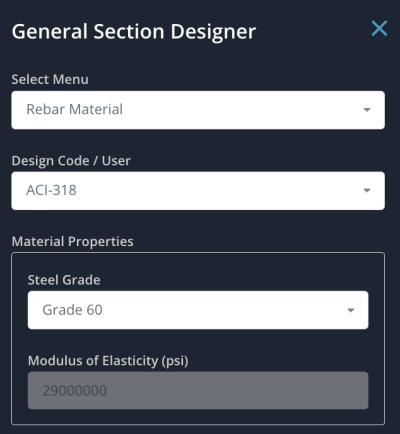
In this menu, the reinforcement properties of the section are defined. The Design Code / User dropdown is again available for selection. We will also use ACI-318 for this input which will update the Steel Grade input. For this example, we will use Grade 60 reinforcement.
Rebar Position Menu
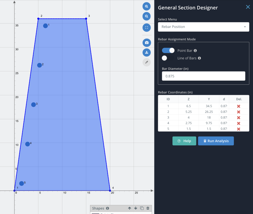
In this menu, we will assign the reinforcement size and position in the section directly. The menu provides two methods locating bars in the section. For this example we will test using both methods, assigning 5 evenly spaced bars to each side of the section (10 bars total). We will also be using the default #7 (0.875″ diameter) bars for the initial check of the section and we will adjust the locations to have approximately 1.5″ of cover.
Method 1: Point Bar
Select this method by toggling on the Point Bar toggle switch. This method involves individually locating each bar and is best suited for irregular reinforcement layouts. On the section visible in the middle of the screen, click to add 5 individual bars along the left side of the section. As we add each bar, a table in the rebar position menu will begin to populate. Once you have added the 5 individual bars, we can refine the locations by manually overriding the reinforcement locations. Adjust the Z and Y ( coordinates of each bar to the following values (Z, Y):
- Bar 1: 6.5, 34.5
- Bar 2: 5.25, 26.25
- Bar 3: 4, 18
- Bar 4: 2.75, 9.75
- Bar 5: 1.5, 1.5
Method 2: Line of Bars
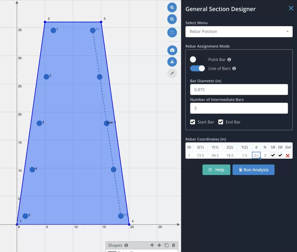
Select this method by toggling on the Line of Bars toggle switch. This method involves locating a line of evenly spaced bars positioned based on a user defined start and end point. This method s best suited for quickly entering regular/repetitive reinforcement layouts. The default options for this method will include a start and end bar as well as 3 intermediate bars. This will give us 5 bars total as required so we can go ahead and locate the bars on the section.
On the section visible in the middle of the screen, right side of the section click the top right corner to set the start position, followed by the bottom right corner to set the end position. You should see 5 bars appear along a line drawn between the two points you specified. We will refine the location of the start and end point to ensure the bars are approximately symmetrical with the individual bars we placed earlier.
Adjust the start (Z1, Y1) and end (Z2, Y2) positions as follows
- Start Position: 13.5, 34.5
- End Position: 18.5, 1.5
Section Loads Menu
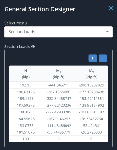
This is where design actions can be input for the analysis. As we accessed the GSD directly from S3D results, the section load data is already pre-populated with loads from the analysis.
Analysis Menu
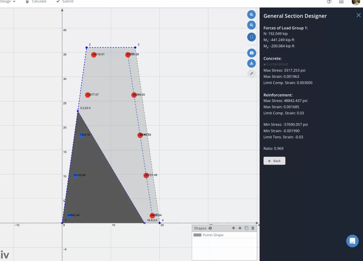
The analysis menu is the final menu and is where a Design Code can be specified for running the section analysis to. For our example, we will set this to ACI-318 and click Run Analysis to check the concrete section. The analysis will run and should return the following analysis results:
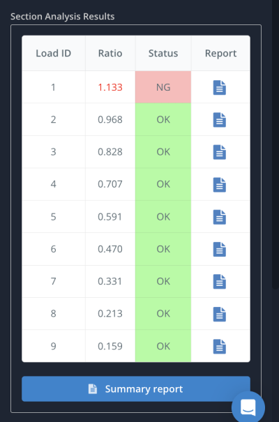
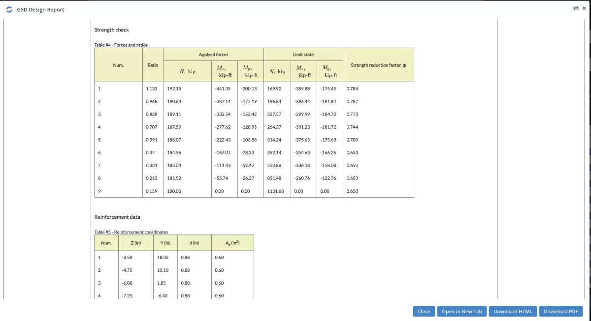
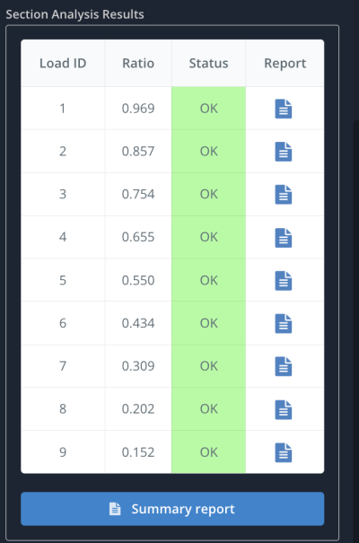
As we can see, the base section has a design ratio exceeding 1 so the design is insufficient and will require adjustment. We can review the individual results for each Load Id or view a summary report which shows the Limit State values compared to the input loads. This report can be downloaded as a PDF for offline storage.
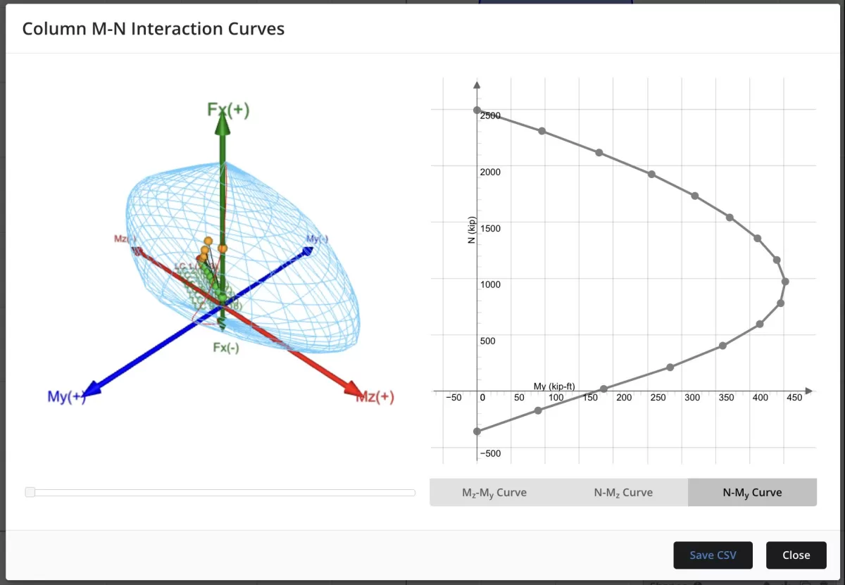
We can also view interaction diagrams defined by a specific angle in the section or view a full 3D column interaction diagram.
Refining the Results
Given that our initial design was insufficient, we can go back and modify the reinforcement to try to improve the capacity. In this case, we will go back to the Rebar Position Menu and we will try increasing the reinforcement to be #8 bars (1″ diameter) for all 10 bars. Rerunning the analysis with the increased bar size finds that the design now passes.

FAQ
The General Section Designer is available with the SkyCiv professional subscription. You can check out pricing for all our accounts here: https://skyciv.com/checkout/
The currently supports the following design codes:
- EN 1992-1-1:2004
- ACI 318
- AS 3600
- CSA A23.3-04
- NSCP 2015
- BS8110
- IS 456
To request support for additional design codes, you can add feature requests here: https://skyciv.upvoty.com/b/section-builder/
Yes, the GSD can be accessed from within the standalone version of the section builder. You will just need to manually assign your section loads.
- Modelling with Plates documentation
- Plate Design Module documentation
- More about SkyCiv Structural Analysis Software – S3D


