
FREE FLANGE PLATE CONNECTION CALCULATOR
SkyCiv Flange Plate Connection Calculator
This flange plate connection calculator checks the moment path through the top and bottom plates and the shear path through the web plate, against AISC 360-16 in LRFD or ASD.
Plates on the beam flanges turn bending into a tension and compression pair, while a separate web plate takes the vertical shear. Splitting the load that way is what makes the joint rigid, and it is why the two paths are checked separately.
Contents
About the Flange Plate Connection Calculator
The calculator works on moment-resisting beam-to-column joints and beam-to-beam splices, reporting design capacities and utility ratios for each.
Field-bolted and shop-welded plate arrangements are both supported, to AISC 360-16 in either LRFD or ASD.
What is a Flange Plate Connection?
A moment connection built from steel plates attached to the top and bottom flanges of a beam. Those plates carry the bending moment into the supporting column or the next beam segment.
The mechanism is worth being precise about: flexure in the beam is converted into a pair of axial forces, tension in one flange plate and compression in the other. Shear does not go that way at all. It is handled separately by a web connection.
Because the two actions travel through different components, the joint gives a rigid, predictable load path, which is what moment-resisting frames need.
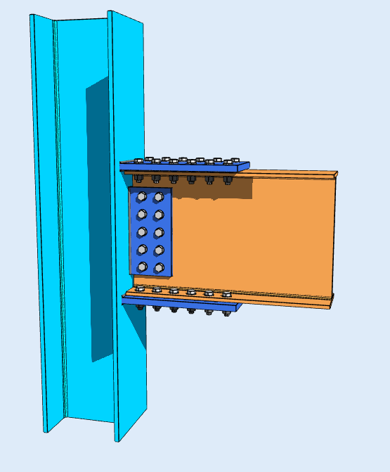
What Components Make Up the Joint?
- Top and bottom flange plates: carry the axial tension and compression that the bending moment produces.
- Web plate or cleat: a single or double shear plate on the beam web, carrying the shear.
- Bolts: high-strength fasteners, typically ASTM A325 or A490, connecting the plates to the beam flanges and web.
- Welds: complete-joint-penetration or fillet welds attaching the plates to the support column or primary beam.
- Column continuity stiffeners: transverse plates inside the column flanges, added where column web yielding or flange bending governs.
The stiffeners are the part most often left out of a first pass. A flange plate can be perfectly adequate while the column it bears against is not.
Where are These Connections Commonly Used?
Wherever continuity and lateral stability against wind or seismic load are needed:
- Moment-resisting building frames and high-rise structures.
- Field splices in long-span steel beams.
- Heavy industrial plant and equipment support structures.
- Crane runway girders and portal frames.
What Types of Flange Plate Connections Exist?
Erection preference and fabrication capacity decide which form gets used:
- Fully bolted: plates bolted to both the beam flanges and the supporting member, in the shop or the field.
- Shop-welded, field-bolted: plates welded to the column flange in the shop, bolted to the beam flange on site.
- Fully welded: plates welded at both ends, for maximum joint rigidity.
- Beam splice cover plates: plates across the top and bottom flanges joining two beam segments continuously.
All four can be checked for capacity and for economy, which are not the same question. The most rigid arrangement is rarely the cheapest to fabricate.
How to Use the Flange Plate Connection Calculator
- Member profiles: the beam and column sections, typically W-shapes.
- Plate dimensions: thickness, width and length for the top, bottom and web plates.
- Fastener and weld details: bolt size, grade, spacing and edge distances, or weld size and length.
- Applied loads: the governing bending moment and shear force.
- Design code and method: AISC 360-16, under LRFD or ASD.
Calculate, and the utility ratios come back with the controlling failure mode and a visual breakdown of where the capacity is being used.
Why Choose SkyCiv’s Flange Plate Connection Calculator?
A moment joint has two load paths and a supporting member that can govern before either of them does. Tensile rupture, block shear, bolt bearing and the column web limit states all have to be worked, and by hand that is a long afternoon per joint.
Automating the AISC 360-16 formulas turns it into a pass or fail you can read at a glance, with a printable report behind it. The value is less in the speed than in being able to check the arrangement you would not otherwise have had time to try.
- Beam Splice Connection Calculator
- Bolt Calculator
- Bolted Connection Design
- Chevron Brace Connection Calculator
- Double Angle Connection Calculator
- End Plate Connection Calculator
- Knee Brace Connection Calculator
- Moment Connection
- Single Angle Connection Calculator
- Single Plate Connection Calculator
- SkyCiv Connection Design Vs. Idea Statica
- SkyCiv Connection Design Vs. Ram Connection
- Weld Calculator
- Welded Connection Design
Common questions about designing flange plate moment connections.
Your Questions Answered

Intuitive Interface
Our easy to learn, powerful to use, intuitive interface allows you to quickly access all the features you need. Packed with smart features like the Pen tool, Repeat/Mirror, and Bulk Editing.Your Content Goes Here

Comprehensive Design Code Support
Our software supports a comprehensive array of steel, wood, and concrete design codes including AISC, EN, AISI, NDS, AS, and CSA.

API Technology
SkyCiv is a customised solution featuring seamless integrations, easy implementations, automated reports and a scalable design and architecture.

24/7 Customer Support
SkyCiv is a customised solution featuring seamless integrations, easy implementations, automated reports and a scalable design and architecture.
