Asymmetrical Sections
Asymmetrical sections are not symmetrical in the vertical y-axis or horizontal z-axis or, in some cases, any axis. Examples of asymmetrical sections are angles and Z-sections.
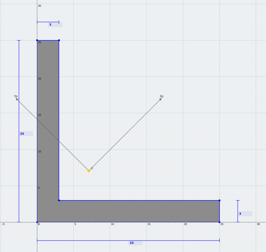
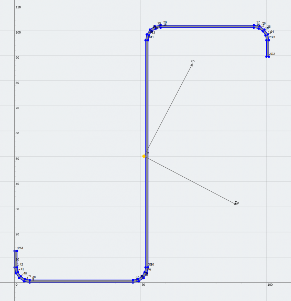
An equal angle and a lipped Z-section (mirror symmetrical about the principal axis)
Beams with asymmetrical sections behave differently to beams with bi-symmetry in bending. Even if the beam has equivalent stiffness in the vertical axis it won’t behave like a RHS and I Shape does.
In this example I’ll demonstrate their behavior with a simple load case: a vertical uniformly distributed load.
Analysis
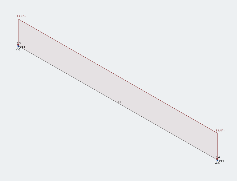
Frame model of an 1.5 m equal angle under vertical UDL
I’ve applied a 1kN/m uniformly distributed load along the full length of this 1.5 m equal angle.
If I wanted to check the deflection at the mid-span of this beam I could quite easily. All I’d need would be the second moment of area, and the standard maximum deflection formula for simply supported beam. A quick calculation using SkyCiv Section Builder and I get the section properties easily.
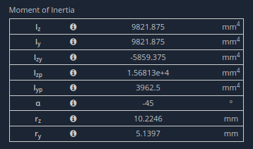
Tabulated section properties from SkyCiv Section Builder
Iz is 9821.9 mm to the 4th power. The section is structural steel with E = 200 GPa.
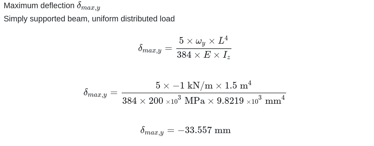
Look at what happens when I calculate this with FEA in SkyCiv Structural 3D.
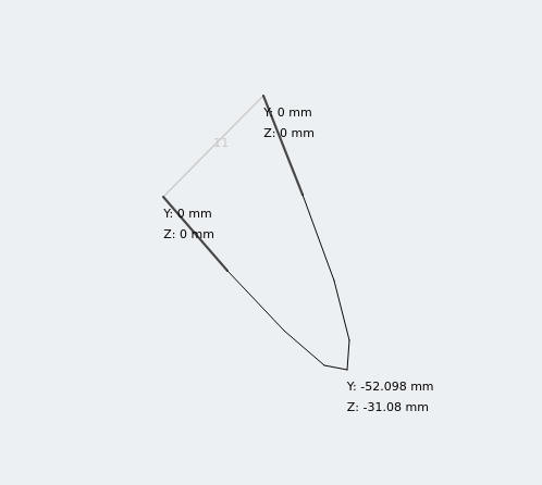
Displacement of equal angle under loading
The equal angle section has two deflection components! Analyzing the deflection of a simply supported beam using a bi-symmetrical section using the previous calculation this would be a perfectly acceptable approach for a quick check. But for asymmetrical sections we need another piece of information.
The angle α
Notice that in the section properties above, the value for α is non-zero.
This means that the principal axis is not parallel to one of the geometric axes.
To demonstrate the effect of rotating the axis on the calculated stiffness values, I’ve plotted below the stiffness in the horizontal and vertical axis as the coordinate system is rotated.
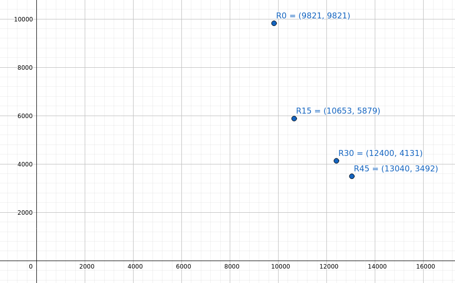
Stiffness of 25x25x3 EA after rotating the coordinate system
Note the non-linear curve that is forming as the coordinate system rotates through 15, 30 and 45 degrees. This curve will be unique to the section.
So why is this happening?
A lecturer told me once that loads follow the stiffest parts of the structure. In this case, the load is being carried by the stiffest axis (the major principal axis).
The correct approach
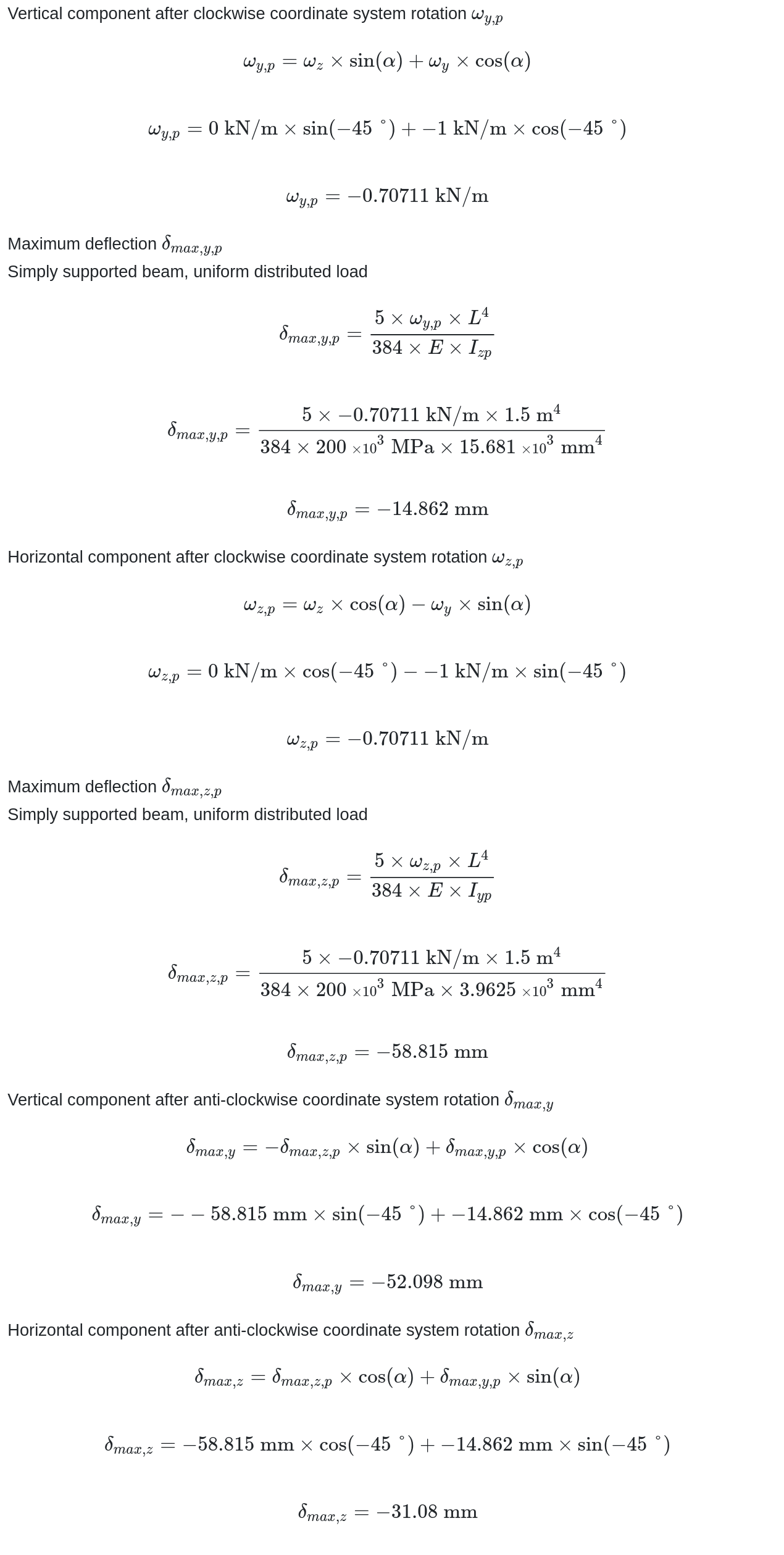
The correct way to calculate the deflection results involves transforming all the loads into the principal axes first, then calculating deflections based on the second moment of area along the principal axes. To prove that this is indeed the correct approach I’ve validated the answer using a hand calculation, and to make this a little more interesting, with a model of the beam using a frame element and, a model built from shells. That way there can be no doubt that the displacements we saw before are indeed correct.
Here is the model I created.
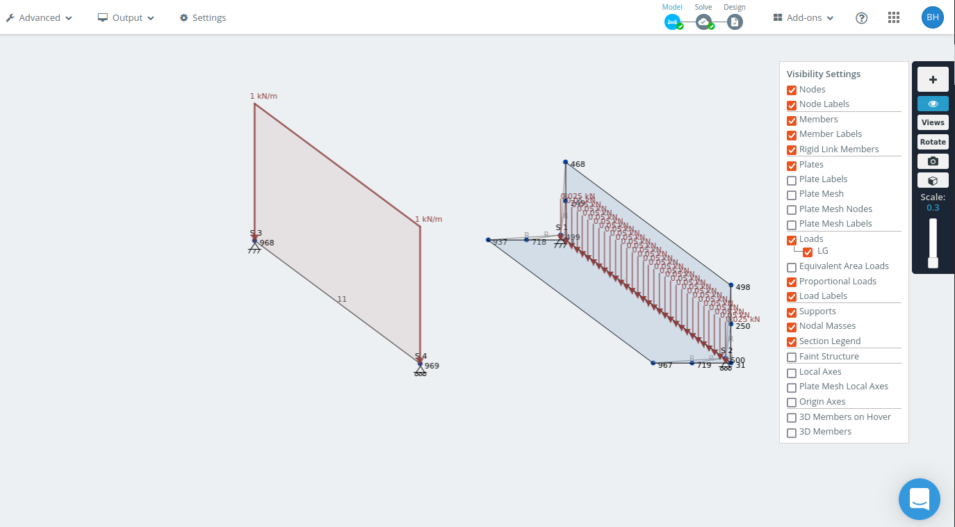
Frame model and shell model of 1.5 m angle
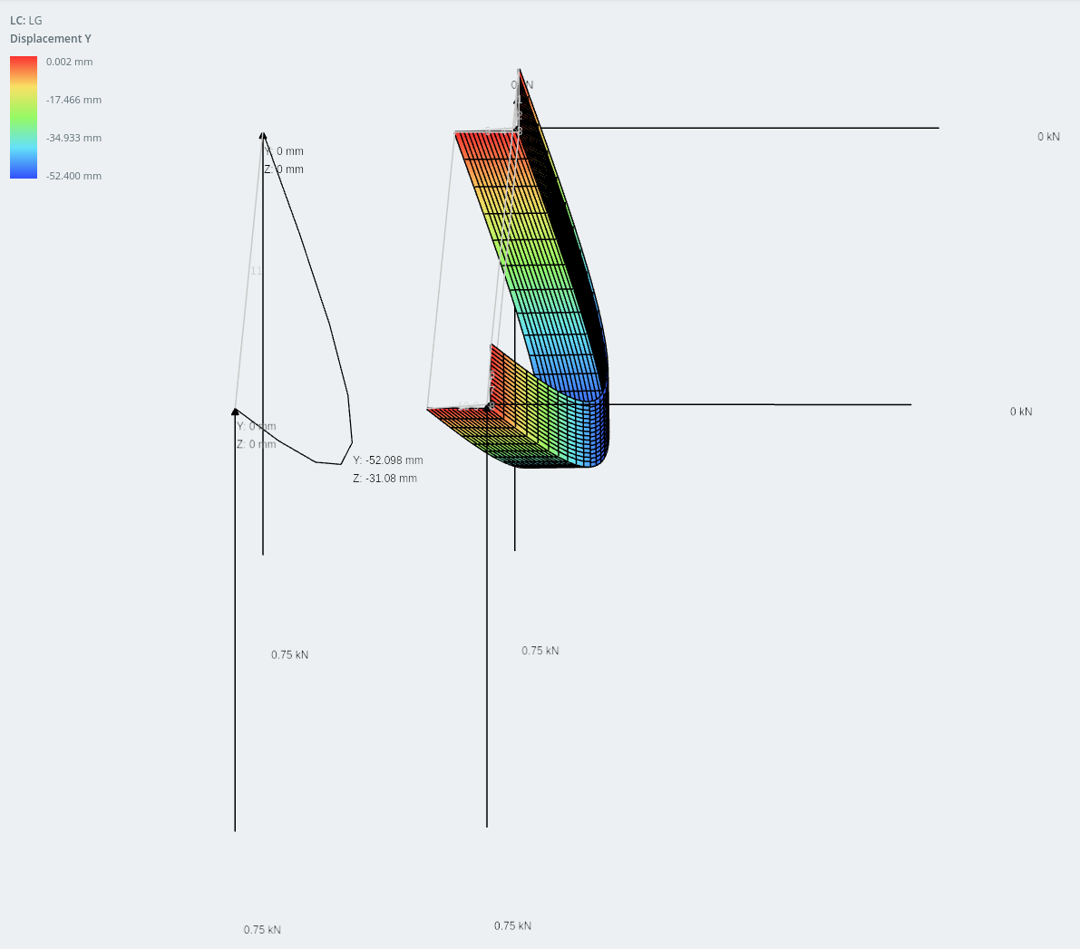
Displacement in the vertical direction
The difference in results between the two models are extremely close: within 1% of each other.
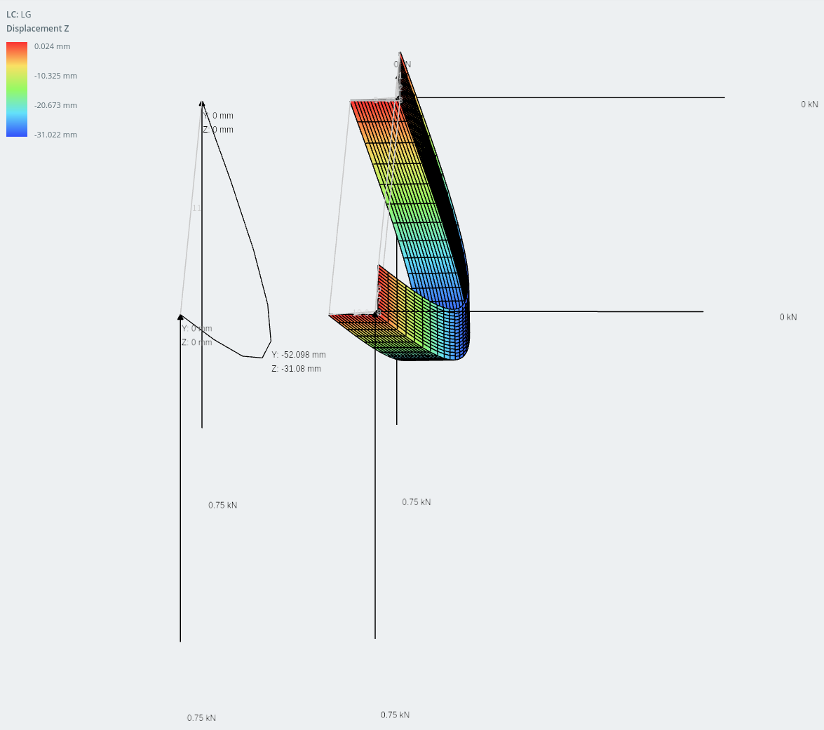
Displacement in the horizontal direction.
And they are confirmed by the hand calculations below.
Why you would want to use these sections?
Engineer like to design structures that are light and efficient, however sometimes there are limitations on the form of structural components, typically due to design decisions by others. This constraint on form could be for many reasons, it may be because an architect wants to hide structural elements for aesthetic reasons, or to comply with local planning laws. It could be that there are limitations due to local fabrication capacity or simply the availability and cost of raw materials. Fabrication costs and coating may also play a significant role. Sometimes, we’re stuck with what we’ve got.
When there is a choice, the section may be chosen because it has certain advantages. Take for example Z sections, which are commonly seen supporting inclined profiled steel sheeting. Typically for small inclined roof angles, channels are more efficient because gravity loads cause only tiny moments about the weak axis. These moments increase as the inclination of the roof increases and at a certain inclination, Z sections become more efficient.
To demonstrate I modeled the lipped-Z section as a 1.5m steel beam. Hopefully after seeing the displaced shape you can see why it would have an advantage on channels.
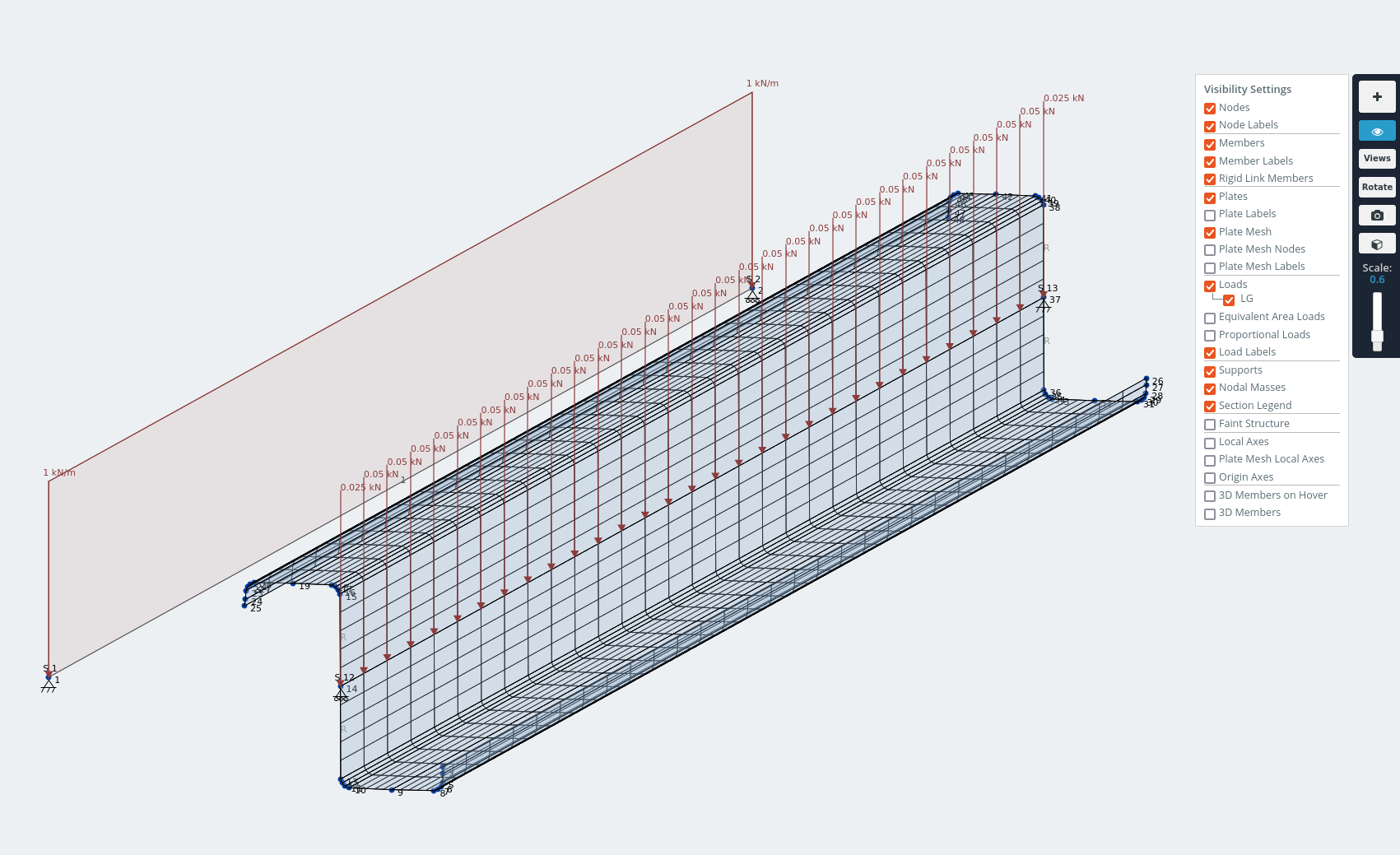
Model of lipped-Z section with 1kN/m distributed load applied through shear center.
The displacement in the z-axis opposes the in-plane shear action of the roof sheeting under gravity loads.
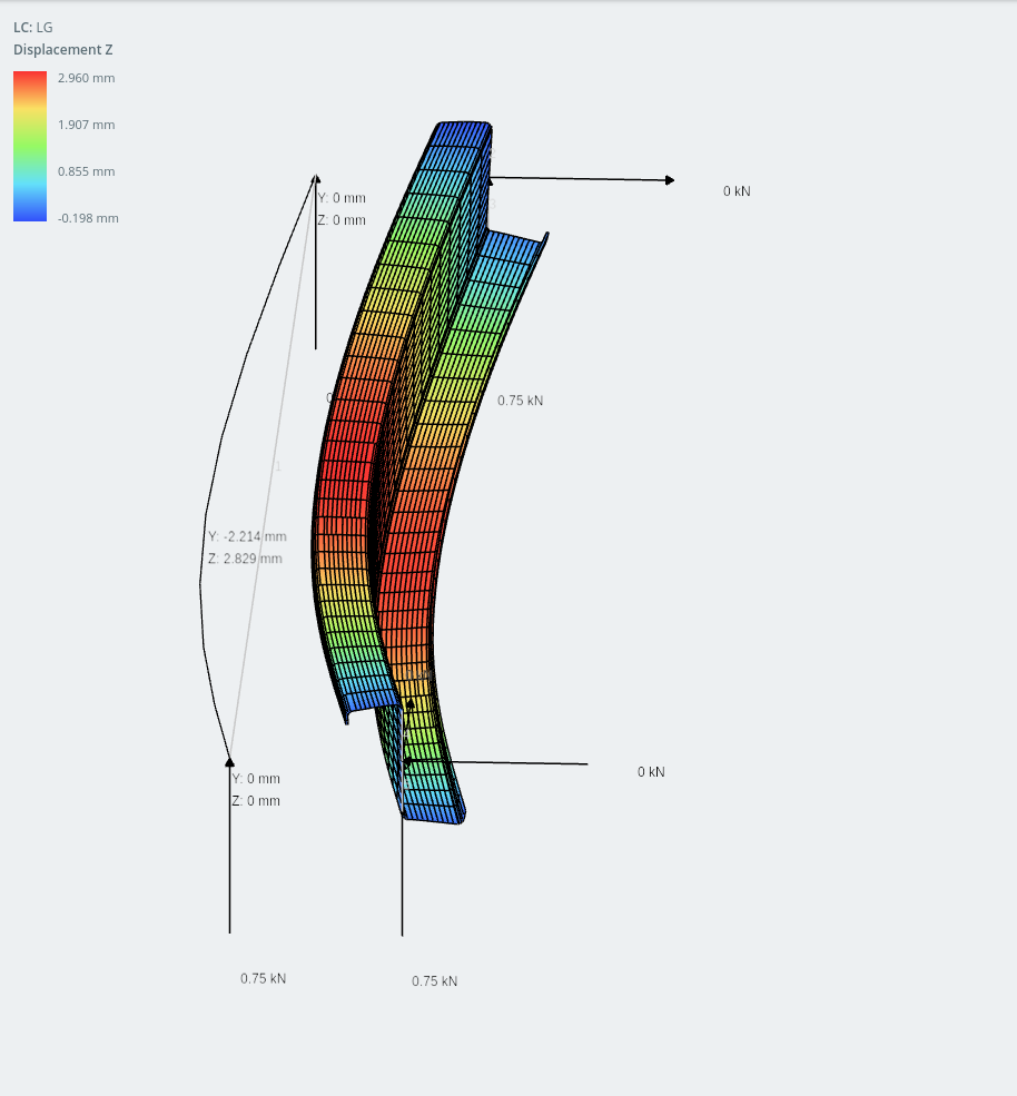
lipped-Z section frame model and shell model (horizontal displacement shown on plates)
Amazingly, the displacement in the y-axis (vertical) is actually less than in the horizontal. I must admit I didn’t expect this type of behavior but with modern cold-forming technology there are so many interesting ways to optimize sections to make them lighter, more efficient, cheaper to fabricate, easier to assemble and easy to handle during construction!
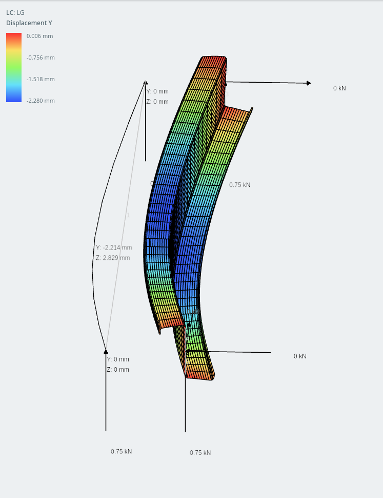
lipped-Z section (vertical displacement shown)
Asymmetrical sections can be engineered to have advantages in some applications. Maybe you consider them in your next design?
I hope you found this post interesting, if you have any questions or feedback about asymmetrical sections, or would like to see more content like this please leave a comment below.


