Design Concrete Elements Using Standalone RC Design

SkyCiv が提供するスタンドアロン RC 設計モジュールを使用してコンクリート要素を設計する方法を学びます。. We will see how to define members, rebar layouts, forces and many more.

他の例を見る

前書き

次のチュートリアルでは, we will learn how to design a concrete element using the Standalone RC Design Module. We will define members, rebar layouts, 力, check reports and optimize our elements.

How to design a cold-formed steel

You have to open the RC Design Module from your SkyCiv dashboard and create a new project using the design code: ACI 318-19.

会員

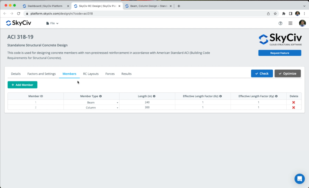
To create concrete elements, we need to go to 会員, in that section we can add ビーム / カラム for our design, for the purpose of this tutorial, we will use the two elements created by default. We can modify the length and effective length factors if needed.

Cold-formed steel design examples - member creation

この係数は、断面に亀裂開口部があるビームたわみの計算に使用されます

We can define a geometry for each of our members, in the case of beams we can select:

  • Rectangle
  • Tee shape

In the case of columns, we can choose between:

  • Rectangle
  • Solid Round

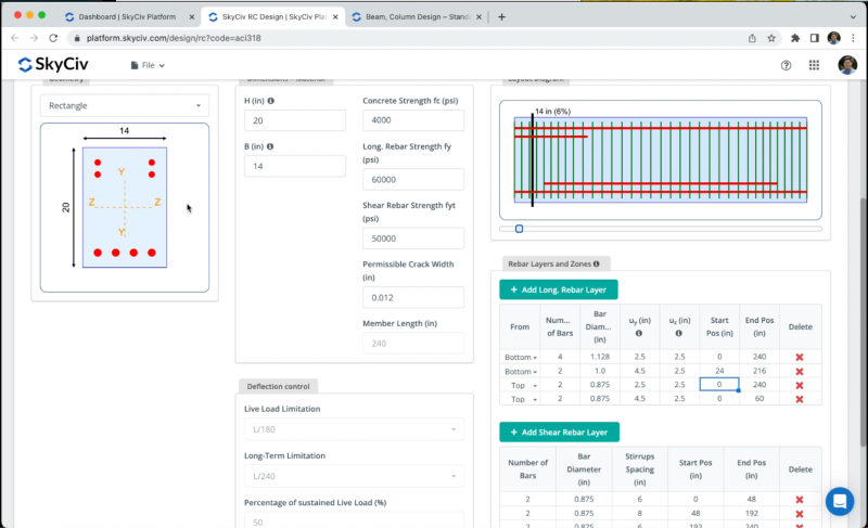
We can also define the dimensions for the members, the beam will have a height = 14 に, Width = 20 に, we will use the material properties obtained by default.

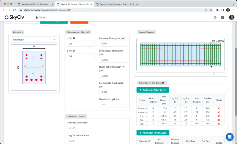
To create rebar layouts we can click on Add Long. Rebar Later または Add Shear Rebar Layer, we will add a top rebar layer at the ends of the beam as shown in the following image:

Cold-formed steel design - sections and materials

After we complete the layouts, をクリックする必要があります Save Layouts.

フォース

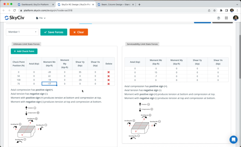
We can define forces for each of our members ( Ultimate Limit State Forces そして Serviceability Limit State Forces ) we can achieve this by clicking on Add Check Point to put the desired forces as shown in the image.

Cold-formed steel building design AISI - loads assignment

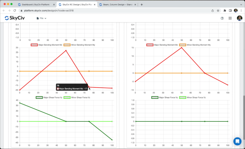
After we defined the forces we can go to the graphs to check the アキシャル, 瞬間, そして 剪断 ダイアグラム.

結果

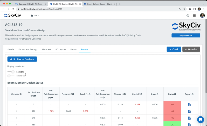
After we defined our members and forces, に行く 結果 > 小切手 to obtain the design checks, we will see results for セクション そして 会員. The sections will show the results for all the sections which correspond to the Check Points defined in the previous chapter. If we select the member’s results, the software will use the worst cases of the section analysis to represent results for each member.

Design a cold-formed steel building - solving the model

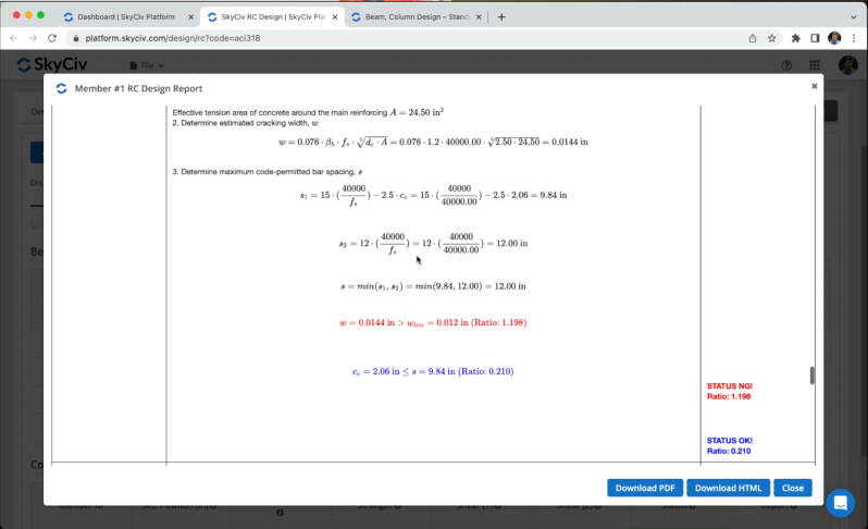
We can open the reports to see all the calculations and validations for each section, we will see step by step all the hand calculations and the status for each verification.

最適化

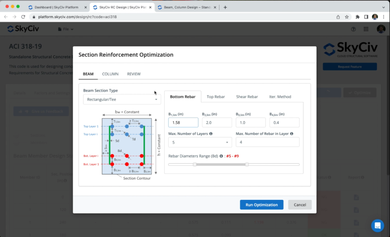
We can optimize the sections reinforcement by clicking on 最適化. We could modify the predefined values, しかしながら, for this example we will use the values by default as shown in the image.

Optimization on Standalone RC Design

After we obtain the optimized reinforcement, クリックできます わかった to see all the results and calculations for our new optimized reinforcement.

よくある質問

After you run the 小切手, you can open the report for the column section and you’ll find the interaction diagram.

Directly on RC design, you can’t design plates, しかしながら, we have another module called プレート設計モジュール that is fully integrated with Structural 3D to design your plates.