SkyCiv で AISC 鋼接合を設計する方法
SkyCiv を使用して鉄骨接合を設計する方法を学ぶ 構造解析ソフトウェア および統合された Steel Connection Design モジュール.
このチュートリアルでは、単純なフレームのモデリングを見ていきます。 (いくつかのショートカットを使って!), 解析結果を確認し、AISC を使用して接続設計を実行します。!
鉄骨フレームのモデリング
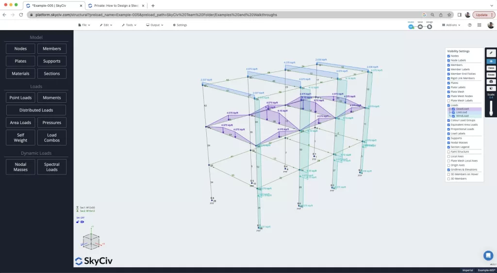
このウォークスルーは、最初に鉄骨フレームを構築することから始めます。. プロセスのこの部分にすでに慣れている場合, 自由にスキップしてください! ただし、このようなモデルを数分で構築する方法を説明します。, SkyCiv のお気に入り機能のいくつかを使用する, 含む:
- ペンツール – ペンツールを使用してすばやくモデルを作成する
- コピーアンドペースト – 部分構造をコピーして貼り付けて、モデルを簡単に構築します
- マルチ編集 – CTRL を押したままマウスをドラッグして、モデルの一部を選択して複数編集します
- 検索セクション – ライブラリからセクションを数秒で追加できます, 検索を使用する
- 面積荷重 – 一方通行, 自動計算される双方向荷重および風荷重面荷重 (そして再調整してください!) メンバーの支流地域.
- 設計コードの負荷の組み合わせ – ASCE をインポート 7-16 組み合わせを自動的にロードする
重要なメンバー部隊の見直し
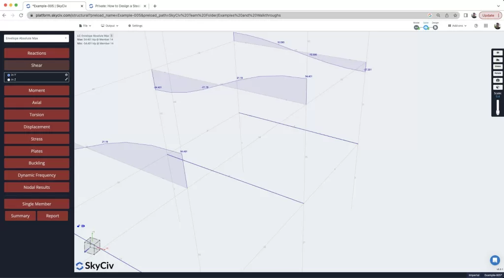
モデルを解決したので、, 解析結果を見て、接続設計の基礎となる最悪の場合の部材力を見つけようとします。. レビューする 封筒絶対最大 結果は、すべての荷重の組み合わせにおける最悪の場合の力を示します。. CTRL キーを使用することもできます + モデルの一部を分離するためのドラッグ機能. モデルをすぐにレビューできるので、これは非常に役立ちます, この図に見られるように、部材端での最悪の場合のせん断力を見つける, メンバーを見る 14 フレーム内で最悪のせん断力が発生する:
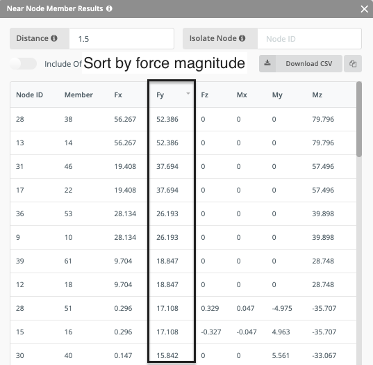
これを識別するために使用できるもう 1 つの便利な機能, それは 節点結果. これは、最悪の場合の結果を視覚的に検査して特定できない可能性がある大規模なモデルで特に役立ちます。. ここでテーブルを並べ替えて、節点での最大の力を簡単に特定できます。, 接続されているメンバーだけでなく. テーブルソート機能はここで非常に便利で、力の方向に基づいて力をソートするために使用できます。, この場合 年度:
せん断結合の設計
したがって、モデル内で最悪の場合の接続を特定しました, この大きさに基づいて接続を設計しましょう. ここでの考え方は、それらをすべて 1 つのタイプとしてデザインするということです。, 設置と建設が容易になります. そう, これを念頭に置いて、右クリックして梁を選択します 14 そしてコラム 35 そしてモジュールを開きます. 多くの情報が解析モデルから取り込まれます, 含む:
- ビーム断面のプロパティ
- 列セクションのプロパティ
- 材料特性
- デザインの力
次に、接続アセンブリの設計プロセスを開始します。. これは接続タイプの選択から始まります (剪断, 瞬間, アキシャルなど。) デザインコードも, この場合AISC. また、他の方向の力が検出された場合、ソフトウェアは黄色の警告でユーザーに警告します。:
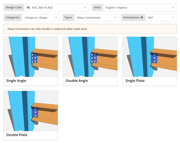
そこから, 接続を選択します, この例ではダブルアングル接続を使用します. 最後に, 梁と柱の両方に器具を設計したい:
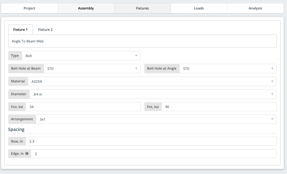
簡単に識別できる入力機能付き, デザインを準備できるまでに数分かかります. グラフィカル インターフェイスは、ユーザーが設計の問題を特定するのに役立ち、同時に設計と入力に関する即時のフィードバックを提供します。. 必須入力完了後, 設計準備が整った接続が必要です:
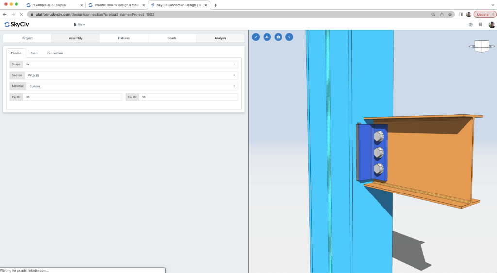
計算の確認
デザインチェックを実行できるようになりました. 結果は明らかです, 有益で簡潔な – 明確な利用率が表示される, 合否基準を色分けして表示:
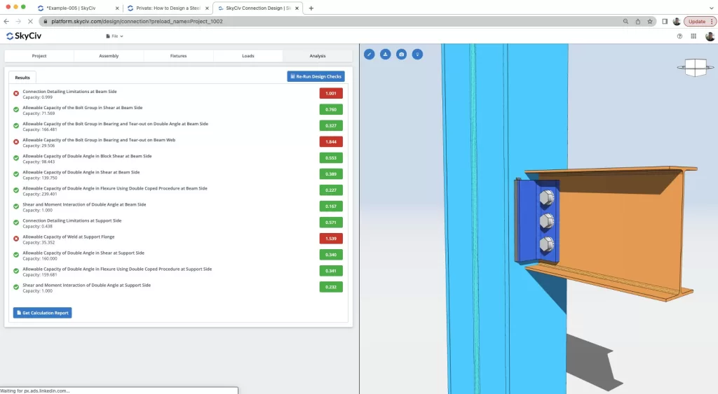
明らかに多くのチェックが実行されています, 細部のチェックから, ボルトチェック, 角度チェック, 溶接チェック, ほんの数例を挙げると、せん断と曲げのチェック. このソフトウェアには強力で明確なレポート機能が付属しています, エンジニアが設計の問題を特定し、設計を改善する最適な方法を理解できるように支援します。:
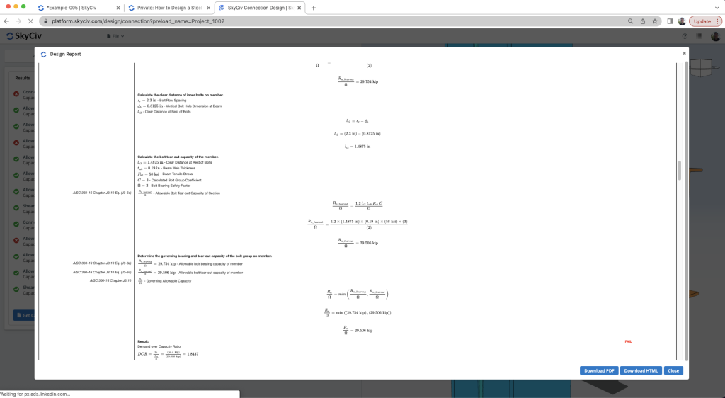
この支援により, ユーザーには、設計を最適化または完成させるために必要なすべての情報が与えられます。. このウォークスルーでは, ユーザーが結果を確認する方法を示します。, デザインを変更してより良い結果を得る.
よくある質問
横ブレースシステムを使用して横荷重に抵抗し、梁にせん断荷重のみを残すことができます。. そうでない場合, 剛性フレームを使用すると、モーメント荷重を伴う接続を設計する必要があり、コストが高くなります。.
上で提案したように構造をモデル化することも、梁の固定性を変更することもできます. また、ビームのサイズをより硬いものに変更して、モーメント荷重が内部荷重としてビームに耐えられるようにすることもできます。.
メンバーがサポートされていることを必ず確認してください. 現在サポートしているのはアメリカとオーストラリアのサイズのみで、I シェイプまたは HSS/RHS/SHS シェイプのみがサポートされています。. また、梁と梁/柱が接続されていて、互いに完全に直角であることを確認してください。.
計算レポートを確認する. すべてのチェックでは、何を変更する必要があるかが直感的にわかるはずです. ボルトチェックに失敗した場合, ボルトの直径やボルトのグレードを変更したり、ボルトの間隔を変更したりできます. 溶接が失敗した場合, 溶接サイズを増やすか、接続の長さを増やして溶接の長さを長くすることができます。. コネクタの場合 (皿, 角度, 等) 失敗する, 厚さまたは長さを増やす. 梁または柱が破損した場合, S3D でサイズを変更するか、接続を大きくしてみてください.


