今日は、SkyCiv Structural 3D でシェル要素を使用してスチール ブラケットをモデル化する方法を検討します。:
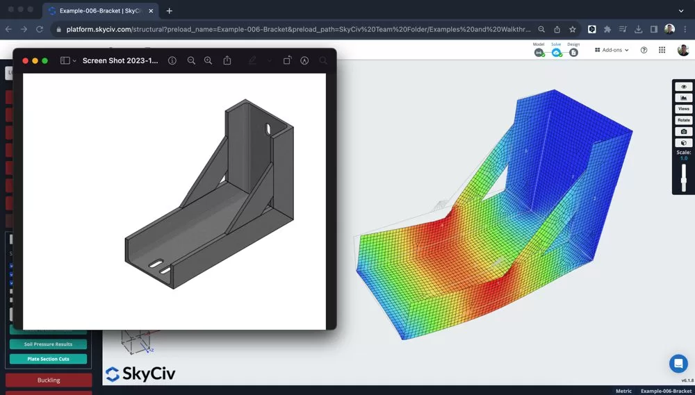
プレートからブラケット/コネクタ モデルを構築する
まず単位を次のように変更します。 んん 構造はより小さなコンポーネントになるため、, この単位系が使いやすくなります. 次に、さまざまなプレートの境界ボックスの配置を開始できます。, チュートリアルのこの部分では, 以下の機能を使用しました:
- 入力演算 – 入力で式を使用する, といった 450/22.5 その値を自動的に計算するには
- ペンツール – 10mmにスナップして接続メンバーをオフにした場合, ノードを非常に簡単にプロットして、最初のプレート要素の境界ボックスを作成できます
- マイボックスのノードをハイライト表示します – 右クリック – プレートを追加
- いくつかのサポートを追加する
ブラケットが 2D で形になりました:
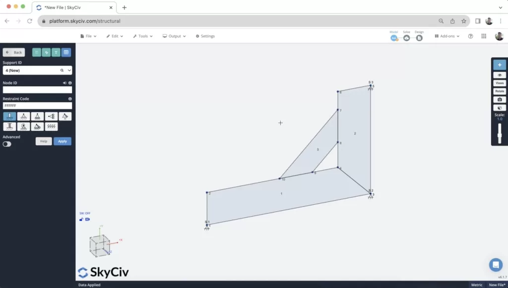
モデルが構築された後、ノードの 1 つに小さな点荷重が適用されました。. これは初期の結果を計算するためのものです, ただし、読み込みについては、このチュートリアルの後半で詳しく説明します。.
プレートのメッシュ化
メッシュプロセスはブラケットのモデリングにおいて非常に重要な部分です. メッシュの品質と要素間の接続は、結果の品質に直接影響します。.
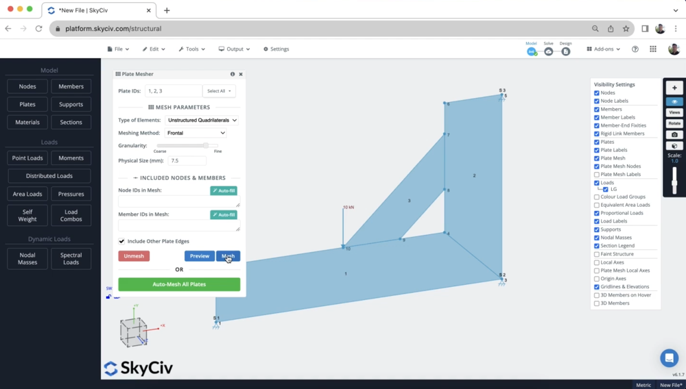
粒度が影響を与える, しかし、それよりも重要なのは、要素が適切に接続されていることを確認することです。 ノードごと. これにより、プレートがすべてエッジに沿って接続されます。. これを確認するには, を使用することをお勧めします メッシュすべて またはすべてのプレートを同時にメッシュ化する, メッシュツールを使用する. メッシュしたいプレートを選択することでこれにアクセスできます (または CTRL キーを押します + あ) そして右クリックします – メッシュプレート:
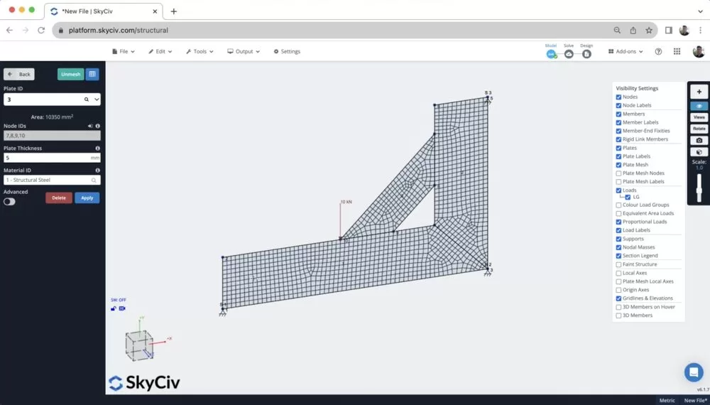
メッシング後, すべてのプレートが隣接するノードで接続されていることを確認して、メッシュを検査することをお勧めします:
いくつかの結果を確認します
モデルを構築したら, ロード, サポートされ、メッシュ化されています, いくつかの結果を得るために簡単な分析を実行できます. 実行した後 静的分析, その後、結果を選択しました ミーゼス 赤の下 プレート 左パネルのボタン. さまざまなプレートの結果があります (メジャー/マイナーな主要なストレス, 膜, せん断など…), さまざまな詳細については、 私たちがサポートするシェル要素の結果. しかし、今のところ, レビューするだけです ミーゼス 結果:
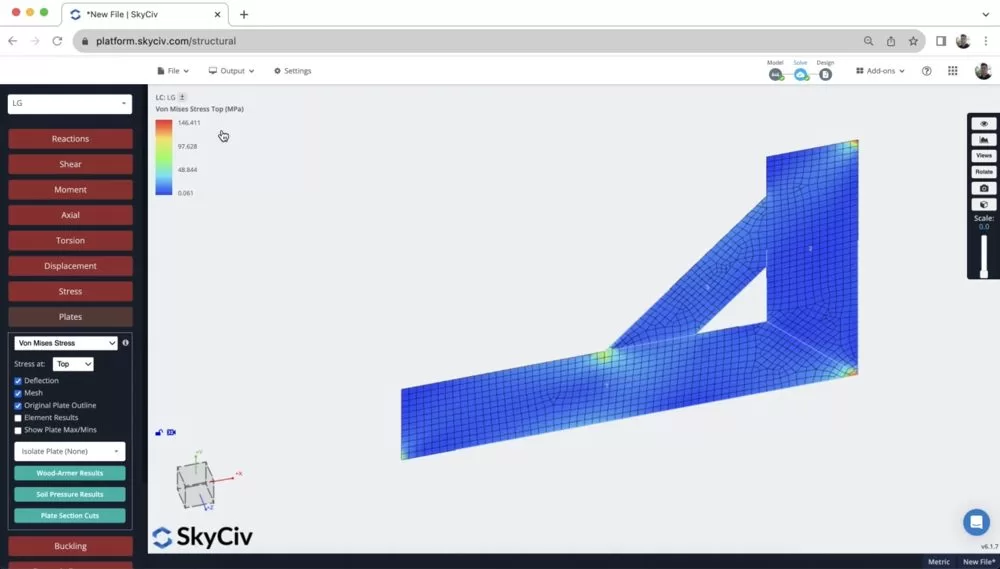
ここから、サポートと点荷重の位置に非常に高い集中荷重がかかっていることがわかります。. このモデルの品質を向上させる方法を検討するので、これに注目することが重要です。 – より現実に近いものにする (このような有限な場所に負荷が集中することはほとんどないため、).
また、移動をアニメーション化するのにも役立ちます (と固定小数点 S マウスをスクロールします) ブラケットがあなたがそれを期待する方法でそらしていることを確認するために. また、3Dでモデルを構築する前に、2Dでレビューをして、時間を節約することも役立ちます.
リジッドリンクを使用してポイントロードを配布します
問題の1つは、ポイント荷重が単一のポイントに集中していることです, これはめったにそうではありません.
そう, 負荷をより小さなコンポーネントに分割できます, または使用します リジッドリンク 力を多くのノードに分配します. 2 番目の戦略を使用します, したがって、単一のポイントロードを行うだけで、将来の変更がはるかに簡単になります。.
接続したいノード間をクリックしてドラッグする. 注意: これをするとき, 引っ張る から 点荷重ノードが常にメッシュ ノードになるように、点荷重ノードをメッシュ ノードに接続します。 マスターノード.
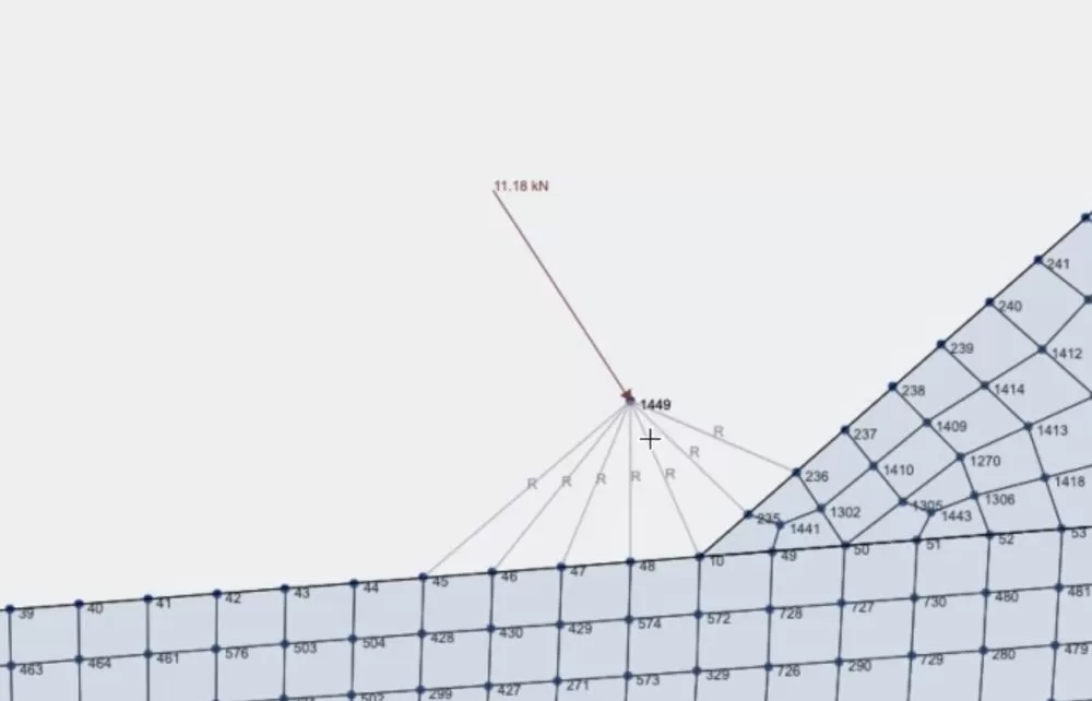
これにより、点荷重のより正確で良好な分散も実現しました。. ストレスは約からなくなりました. 100MPa~50MPa程度:
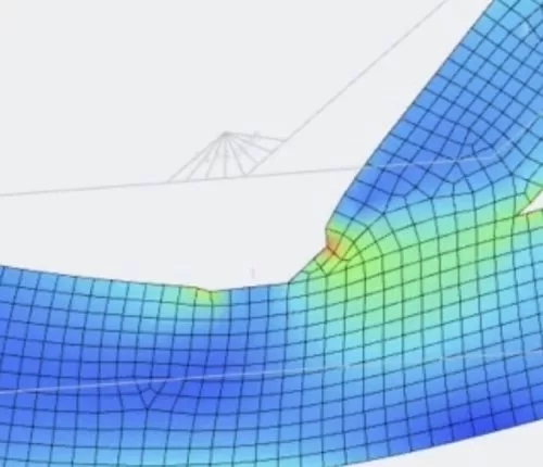
3D でモデルを構築する
2Dの結果に満足したら, 今こそ3Dでモデルを構築するのは良い考えです. そうするために, 私たちはこれらのモデリング機能を最大限に活用しています:
1. コピーアンドペースト – モデル全体をコピーします (NS + あ) その後 (NS + C). 貼り付けに行くとき (NS + V ) 参照ノードを選択するように依頼します. の参照ノードを使用しました 0,0,200 そこで、Z軸に沿って200mmの2番目のブラケットを貼り付けました:
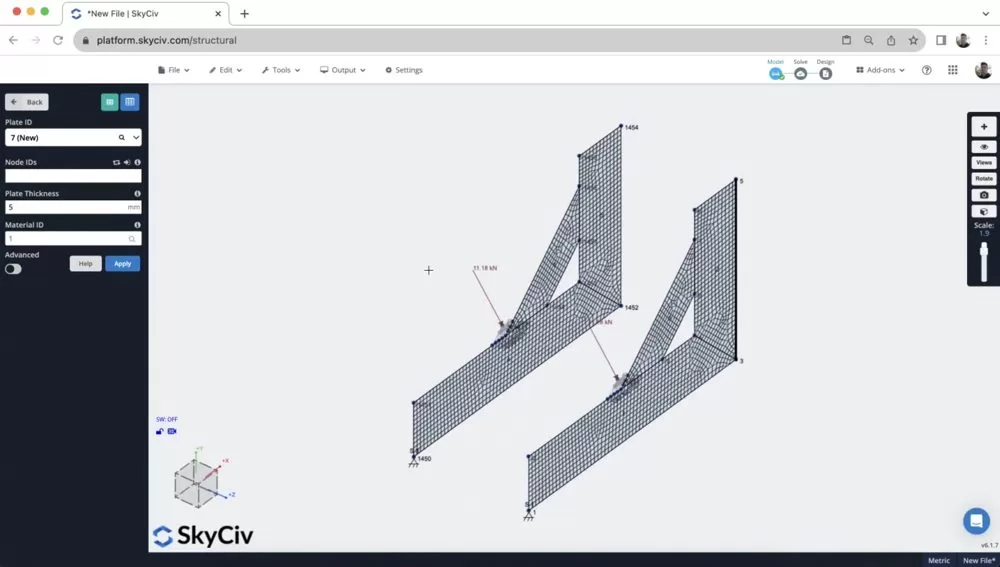
2. 右クリック – プレートを追加 – その後、プレートを追加しました (私がステップでやったのと同じように 1), Ctrlを使用します + ドラッグして選択します 4 コーナーノードと右クリック プレートを追加. リメッシュ後, これでモデルが完了しました:
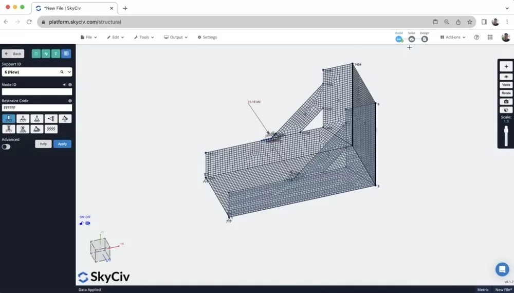
3. 他のパーツを追加する – このチュートリアルでは紹介されていません, しかし、次のような機能も使用できます 穴のカットアウト そして 曲線要素 より複雑な形状のプレート用. 注意: これは通常、メッシュ作成前に行われます.
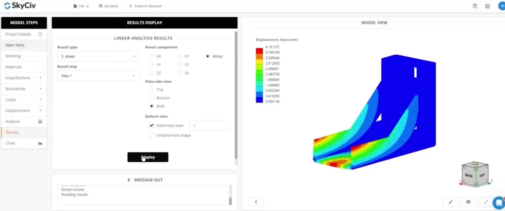
[ボーナス] SkyCiv FEA でこの構造をモデル化する
- SkyCivは、これらの複合形状を変換セクション法で処理します – 押し出したい断面のDXFをインポートすることから始めることができます
- プレートプロパティを追加します – プレートの厚さを割り当てます, カットアウトとモデルのその他の側面
- エッジを追加します – ブラケットの外側のエッジを追加します
- 負荷とサポートを適用します – ノードのグループに単一のポイント負荷を適用できます, 厳格なメンバーは必要ありません
よくある質問
剛性リンクのさまざまなノードプロパティを理解することが重要です (注意, これらは硬質ダイヤフラムの場合も同じです)
- マスターノード: マスター ノードは、剛体リンクの動作を制御する参照ノードです。. 何らかの形で固定または制約されたままになる, そして、このノードの動きや変形が剛体リンク全体の動作を決定します。. マスター ノードは通常、プライマリ構造またはコンポーネントに関連付けられます。.
- スレーブノード(s): スレーブ ノードはリジッド リンクを介してマスター ノードに接続されます。. これらのノードはマスター ノードの動きと変形を模倣します。. 本質的に, マスターノードが移動するときに正確に移動するように制約されています. 奴隷ノードは通常、一次構造に硬く接続されている二次構造またはコンポーネントに関連付けられています.
a マスターノードは別のマスターにとって奴隷になることはできません. したがって、厳格なメンバーを設定するとき, マスターから多くの奴隷ノードに接続することが重要です。. 各剛性メンバーには同じマスターノードが必要です.
あなたのプレートにカットアウトを追加します, まず、カットアウトが配置される場所の輪郭を示すノードを追加することから始めます。. 注意, ここではカーブメンバーツールを使用すると役立つことがよくあります.
プレートを右クリックすると、, カットアウトノードがある場所, をクリックします プレートのカットアウト
構造3D, 現在、サポートしています 線形分析 のみ. SkyCiv Shell FEA ではより高度な分析を使用できます, 含む:
- 線形 (静的)
- 非線形座屈
- 幾何学的非線形 (静的)
- 幾何学的な + 材料非線形 (静的)
- 幾何学的な + 材料非線形 (明示的な)


