Designing a Steel Bracket/Connector Using Shell Elements in SkyCiv
Learn how to easily model a steel bracket using SkyCiv Structural 3D, using plate (shell) elements.
This tutorial uses meshing, rigid links, line supports and modelling features such as Copy and Paste to model a steel bracket in minutes.
Today we will be exploring how we can model a steel bracket using shell elements in SkyCiv Structural 3D:
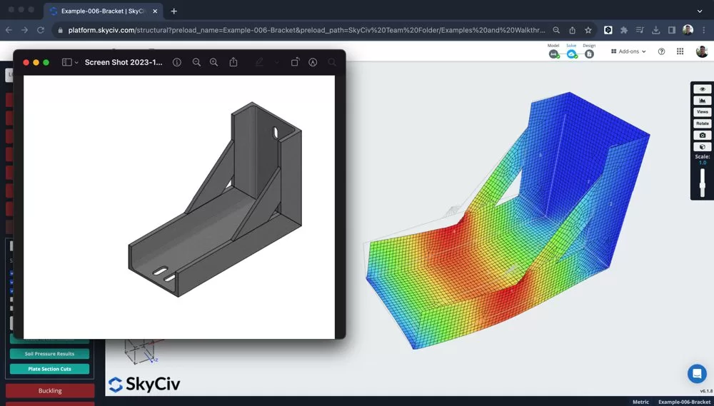
Building your Bracket/Connector Model out of Plates
Starting by changing the units to mm since the structure is going to be a smaller component, so this unit system will be easier to use. We then can start putting in the boundary box of the different plates, in this part of the tutorial, I used the following features:
- Input arithmetic – using an expression in the input, such as 450/22.5 to automatically calculate that value
- Pen Tool – with snapping to 10mm and turning off connecting members, I can plot nodes quite easily to create the bounding box of my first plate element
- Highlight the nodes of my box – right click – Add Plate
- Adding some supports
The bracket is now taking shape in 2D:
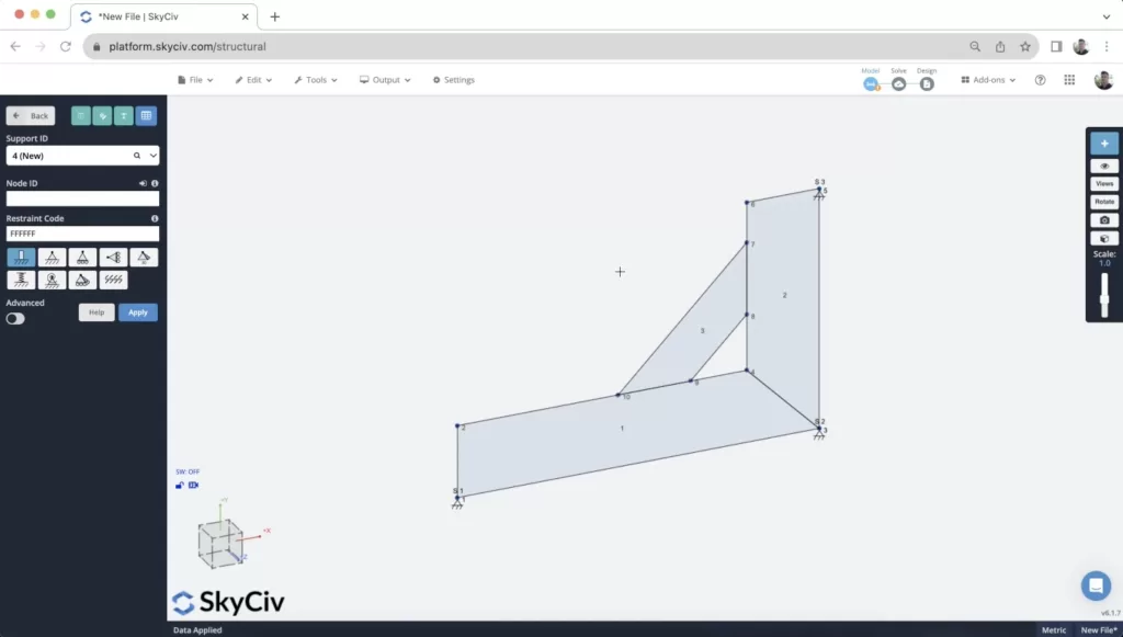
After the model has been built a small point load was applied to one of the nodes. This is to calculate some early results, but loading is explored in more detail at a later point in this tutorial.
Meshing your Plate
The meshing process is an extremely important part of modelling a bracket. The quality of your mesh and the connectivity between your elements will directly effect the quality of your results.
The granularity plays an effect, but more importantly it is important to ensure your elements are properly connected by nodes. This ensures the plates are all connected along their edges. To make sure of this, we recommend using the MeshAll or Meshing all your plates at the same time, using the Mesh Tool. You can access this by selecting the plates you wish to mesh (or hit CTRL + A) and then right click – Mesh Plates:
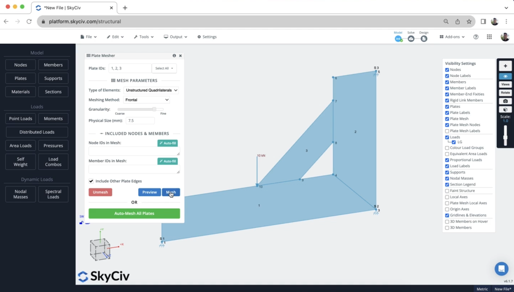
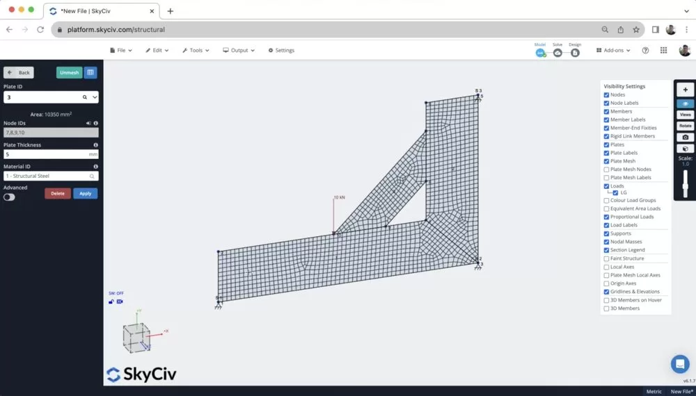
After meshing, it’s a good idea to inspect the mesh to ensure all plates are connected by adjacent nodes:
Reviewing some Results
Once we have the model built, loaded, supported and meshed, we can run a quick analysis to get some results. After running a Static Analysis, I then selected the results for Von Mises under the red Plates button on the left panel. There are a number of different plate results (Major/Minor Principal stresses, membrane, shear etc…), for more information on the different shell element results we support. But for now, we can just review the Von Mises result:
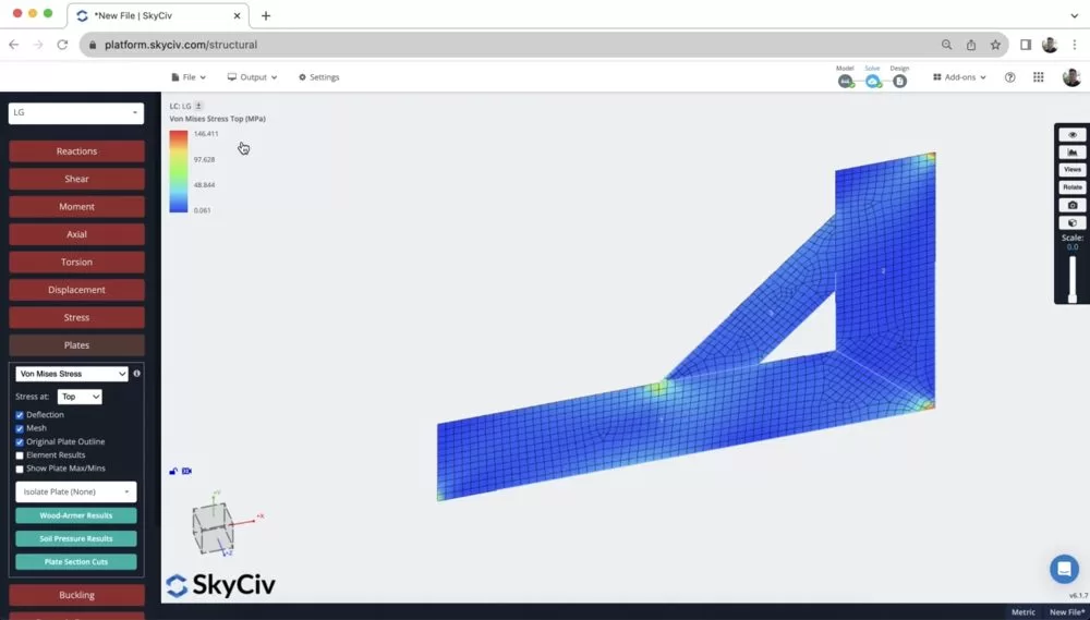
From here it is noticeable that there are very high concentrated loads at the supports and the location of the point load. This is important to notice as we will explore how we can improve the quality of this model – making it more true to life (since loads are rarely concentrated at such a finite location).
It’s also helpful here to animate the displacement (hold down S and scroll your mouse) to make sure the bracket is deflecting in a way you’d expect it to. It’s also helpful to do a bite of a review in 2D before building your model out in 3D to save yourself time.
Distributing your Point Load using Rigid Links
One of the issues is that the point load is concentrated at a single point, which is rarely the case.
So, you can either split the load into smaller components, or use rigid links to distribute the force to a number of nodes. We will use the second strategy, so we just have a single point load which will make future modifications much easier.
By clicking and dragging between the nodes you want to connect. Note: when doing this, drag from the point load node to the mesh node to ensure point load node is always the Master Node.
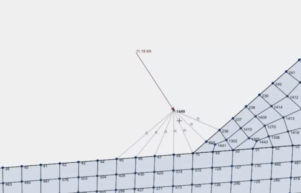
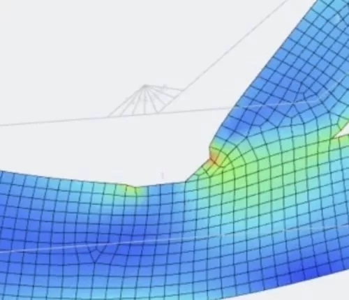
This has also resulted in a more accurate and better distribution of the point load. The stress has gone from approx. 100MPa to around 50MPa:
Building out the Model in 3D
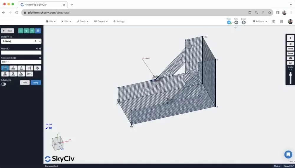
Once we’re happy with our 2D results, now is a good idea to build out the model in 3D. To do so, we are making the most out of these modelling functions:
1. Copy and Paste – Copying the entire model (CTRL + A) then (CTRL + C). When I go to paste (CTRL + V) it will ask me to select a reference node. I used a reference node of 0,0,200 so it pasted the second bracket 200mm along the z axis:
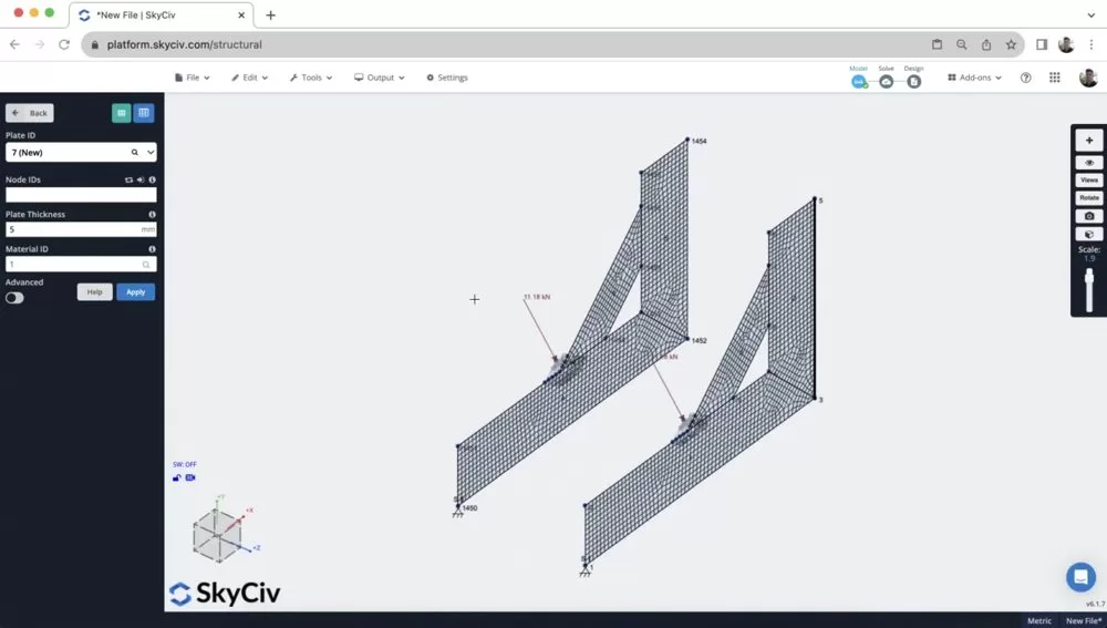
2. Right Click – Add Plate – I then just added plates (the same way I did in step 1), using CTRL + drag to select the 4 corner nodes and then right clicking Add Plate. After remeshing, we now have our model completed:
3. Add other Parts – not featured in this tutorial, but you can also use features like Hole Cutouts and Curved Elements for more complex shaped plates. Note: this is normally done pre-meshing.
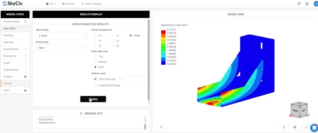
[BONUS] Modelling this structure in SkyCiv FEA
- Import DXF – You can start by importing a DXF of the cross section you wish to extrude
- Add plate properties – Assign the plate thickness, cutouts and any other aspects to your model
- Add Edges – add the outer edges of the brackets
- Apply Loads and Supports – a single point load can be applied to a group of nodes, with no need for rigid members
FAQ
It’s important to understand the various node properties of a rigid link (note, these are the same for rigid diaphragms)
- Master Node: The master node is the reference node that controls the behavior of the rigid link. It remains fixed or constrained in some way, and the movement or deformation of this node dictates the behavior of the entire rigid link. The master node is typically associated with the primary structure or component.
- Slave Node(s): The slave nodes are connected to the master node via the rigid link. These nodes mimic the movements and deformations of the master node. Essentially, they are constrained to move exactly as the master node moves. The slave nodes are typically associated with secondary structures or components that are rigidly connected to the primary structure.
It’s important to note that a Master node can not be a slave to another Master. So when setting up your rigid members, it’s important to connect FROM the master to a number of slave nodes i.e. each rigid member should have the same master node.
To add a cutout to your plate, first start by adding the nodes to outline where your cutout will be. Note, using the curve member tool is often helpful here.
You can then right click the plate, where your cutout nodes are on, and click Plate Cutout
In Structural 3D, we currently support Linear Analysis only. More advanced analysis can be used in SkyCiv Shell FEA, including:
- Linear (Static)
- Non-linear Buckling
- Geometric Nonlinear (Static)
- Geometric + Material Nonlinear (Static)
- Geometric + Material Nonlinear (Explicit)


