For John Morey, a lifelong interest in hill climb race cars leads to an amazing project aided by SkyCiv. Growing up reading everything about motorcycles and cars, fixing and modifying them, he concluded that he wanted to be the person making the decisions when it came to putting things together. From the ages of 20-22, he owned a racing car that was eventually ruined via a crash. 50 years later, he has rekindled his passion for the sport and is passionate about constructing a new car.
Type: Mechanical
Engineer: John Morey
“I cannot convey to you how easy and useful your program was to use, and it made a significant difference to the project.”
About the Project
For this project, John wanted to create a simple yet light and powerful hill climb race car, starting with a scaled-up go-kart and a 1300cc engine. At the moment this was released, John was working on actually constructing his dream, and we are very excited to see it upon completion!
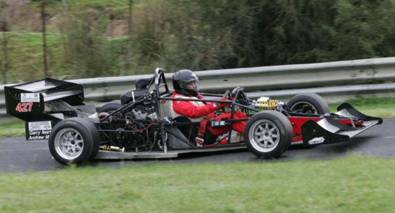
Figure 1: Similar hill climb race car to the one designed by John
The Challenge
The main priority of this project was driver safety, leading to the development of a 3D space frame design. A large amount of work went into trying to scale up the frame from a small model to life-size. Primarily, the challenge here is trying to retain the stiffness and lightness for the forces that would be seen during the race.
In this case, single-seat open-wheel hill climb cars participate in the “Formulae Libre” class, which means the cars in this competition are not affected by many rules, making the engineering decisions easier and more forgiving.
Differing types of suspension needed to be considered here, but the “wishbone” design was chosen by John and his team. To maximize downforce for the car, John was able to get the overall width of the car to 2.5 meters, as wide as the trailer required. These larger plan dimensions give the car more surface area underneath the car, aiding with downforce at high speeds, which is extremely important at sharp turns and corners.
Another technical aspect of this challenge is the car’s acceleration. According to John, acceleration must not be power limited at full speed. To achieve this requires 4WD and about 400 HP which is quite possible with a supercharged 1300 cc engine. It only requires a “feather throttle” off the line, but at full speed & downforce, a huge power transfer is possible.
A summarizing sentiment from John:
“The project logically moved from the simple to the complex over many years of iterations, while retaining the stiffness, low weight, and driver safety.”
How it Was Designed
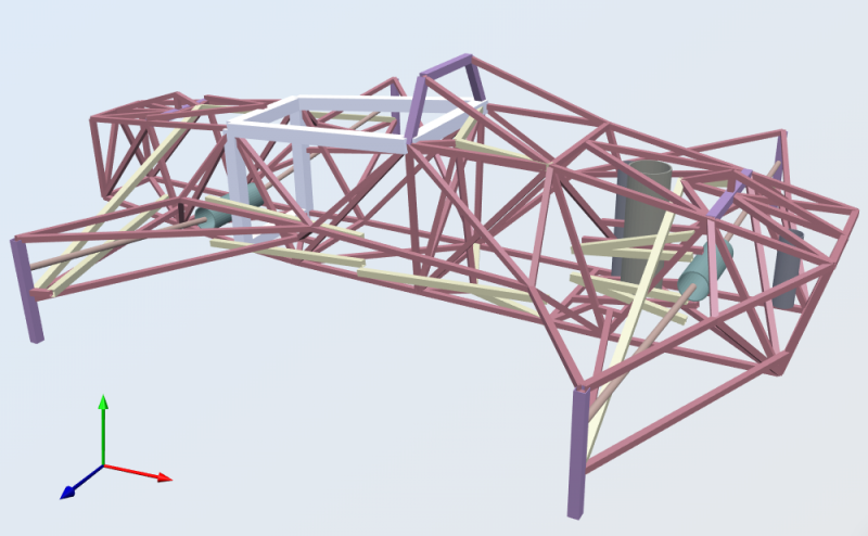
Figure 2: 3D rendering of finished SkyCiv Structural 3D product
Uphill climb race cars have been around for a while, so there is quite a bit of existing, general knowledge of the industry including the minimum weight, wall thickness, constructability, safety recommendations, etc. For this project, the “wishbone” suspension design meant that extra bending strength of the connecting tubes would be needed.
By hand, space frame design when assuming pin joints is extremely time-consuming for a project like this. Engineers who go this route tend to make mistakes, and because in practice welded joints (fixed connections) exist, it would be basically impossible to complete by hand. This is where SkyCiv came into play for John.
Generating the frame’s geometry in SkyCiv of the project turned into a learning process for John. He started with a small aspect of the car using measurements taken from hand-drawn drawings done by John, starting with the driver’s hoop. He realized these calculations by hand were going to be difficult, so he gradually added more and more to the small structure he had as he learned how to use the SkyCiv platform.
As for the spring suspensions, John decided to model these as rigid frame tubes, as he was concerned with forces and stresses, not spring deflection.
“Amazingly I was able to do it after a few hours, and the answers made sense in terms of the stresses I had hand calculated, so I started to add to my single rectangle model and ended up with the whole car, including chain drive clearance and suspension pushrod clearance.”
Going from acceleration and forces in g’s was quite easy for John using SkyCiv. Basic free body diagrams inside and front elevation with acceleration in g’s were used to work out loads given the weights of the frame, which were given to him automatically from SkyCiv.
For John, it was also clear that the driver’s upper body and legs preclude diagonals across those rectangles, so they have been roughly designed by hand as beams. He found out during the straightening of my space frame 50 years ago that about 90% of the torsional flexibility occurs in these 2 rectangles, in an otherwise well-triangulated space frame.
The wishbone load cases & stress calculations were done by hand initially with free-body diagrams, made simpler than the exact situation, so I could do a hand calculation, and then with extra safety factor added.
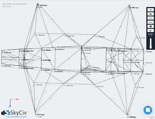
Figure 3: Plan view deflection results for an example load case
How SkyCiv Helped
For most mechanical projects like this one, extremely robust and complex software is needed for the analysis of complex, machined parts. For John though, he was able to take advantage of the quick and easy modeling and analysis features of Structural 3D – a module not commonly used for the racecar frame design. Usually used for structural building and frame design, he was able to flex the versatility of the SkyCiv platform for his awesome project.
At the beginning of the project, it was imperative for John to confirm some hand calculations he had completed but more importantly, find out the deflections of his frame. The load cases for 3 g cornering, 3 g braking, 3 g acceleration, 3 g bump were easy to apply according to John.
“…the linear stress/deflection results were easy to understand on the rendered model, which also has really good shadowing.”
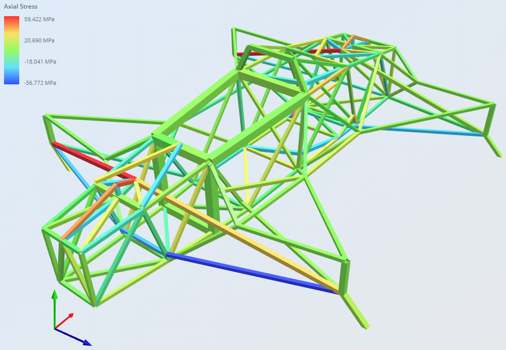
Figure 4: 3D rendered Structural 3D Axial stress results from downforce and cornering loads on the frame
Without a software aid, he fully expected to give up when it became too much. Knowing the forces at hand with the operation of the car, John was able to use the Analytical solver in Structural 3D to get the stresses of his frame members and their resulting deflections.
John speaking on the value of the 3D rendering and depiction of analytical results:
“I found several interferences that were not evident from my drawings and were able to improve several difficult diagonal member positions. This showed the way for many other small but important chassis shape changes and saved many hand-drawn pages of changes.”
Stemming from the application of 3g cornering, braking, acceleration, and “bump” load cases, John used the deflection results to cross-check his hand calculations and verify them, allowing him to make cross-sectional changes to his space frame. This was necessary to optimize both the weight and stiffness of the car’s frame. For example, he ends up needing to increasing the size of the frame around the driver’s legs and hip area for increased crash safety.