File ManagerAccount SettingsAccessing The SoftwareSupportTeam ManagementFull Demos
Certification
Solving a simply supported beam is a relatively simple task that can be done manually with relative ease. Although, there are times when you require the results really quick when you adjust certain parameters in your beam. In these situations, a beam solver would be rather useful in cases when results are need much quicker for different situations. This is where SkyCiv Beam can be extremely useful.
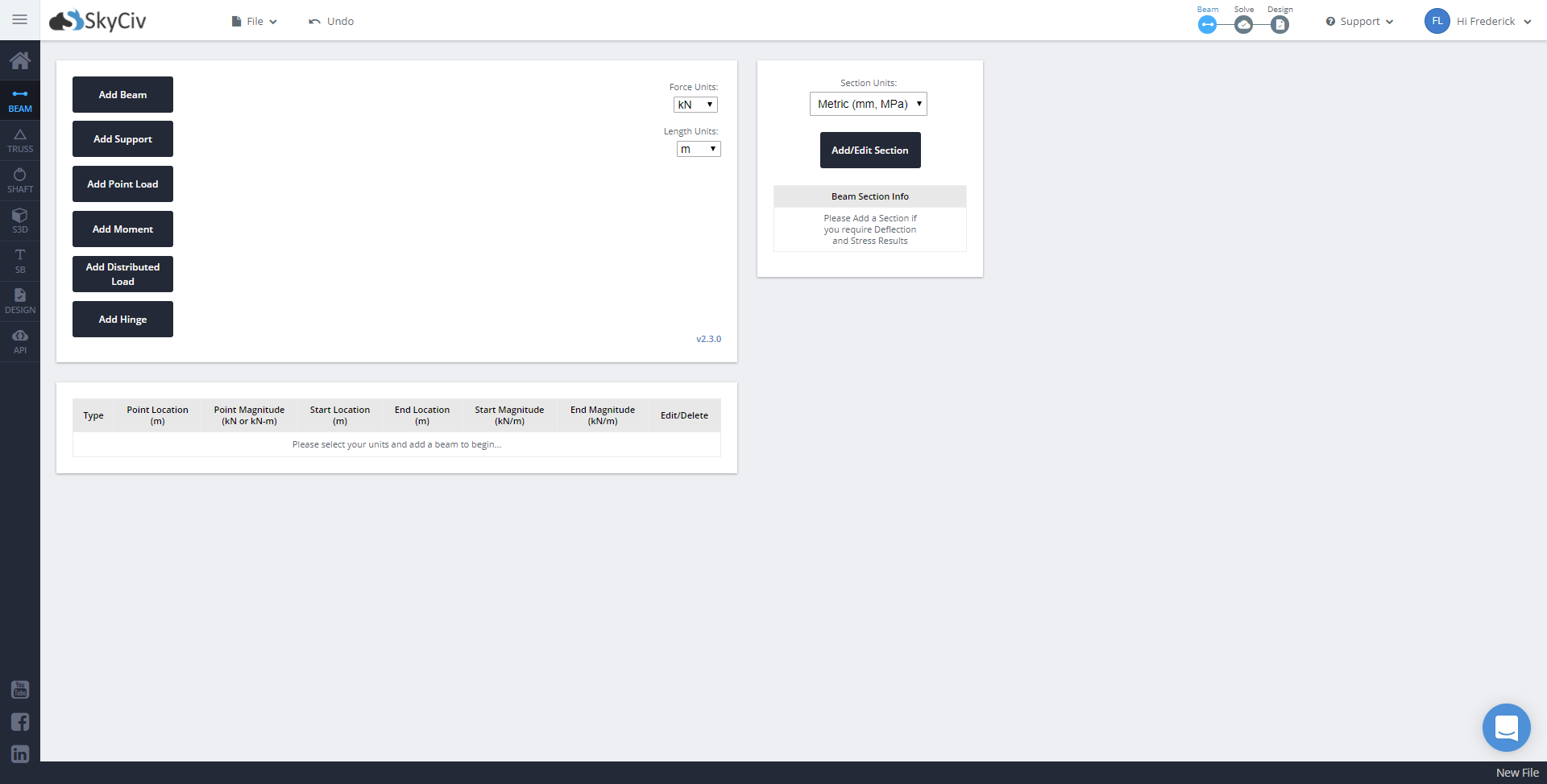
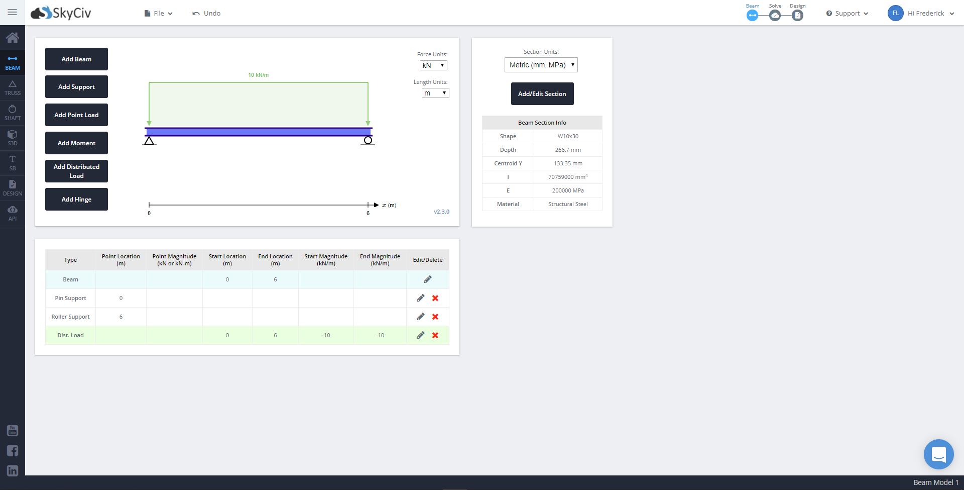
In this situation, we will create a 6 meter simply supported W10x30 steel girder using SkyCiv Beam. SkyCiv Beam has a relatively simple interface that each option available in the program is as straightforward as the captions written on them.
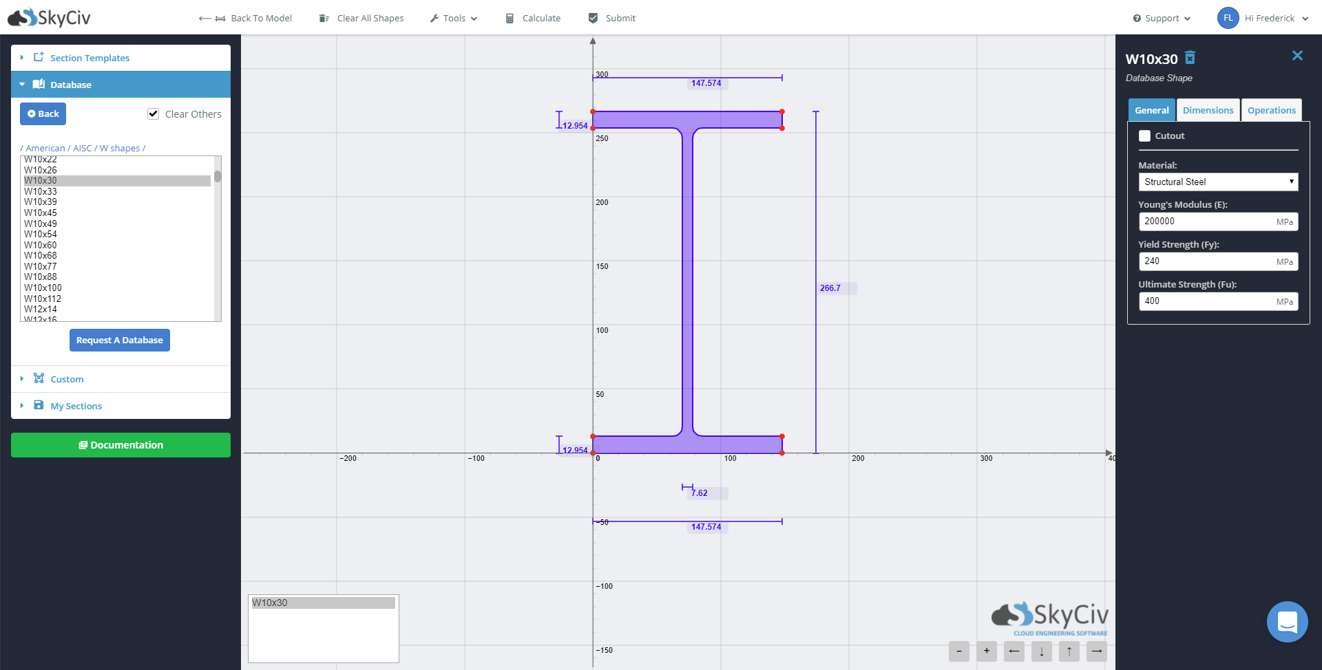
Continuing further, we will add a W10x30 section, which directly takes us to the Section Builder of the SkyCiv platform. The section should appear under the Database > American > AISC: W shapes > W10x30. For simplicity’s sake, we will leave the material, dimensional and translational properties as is.
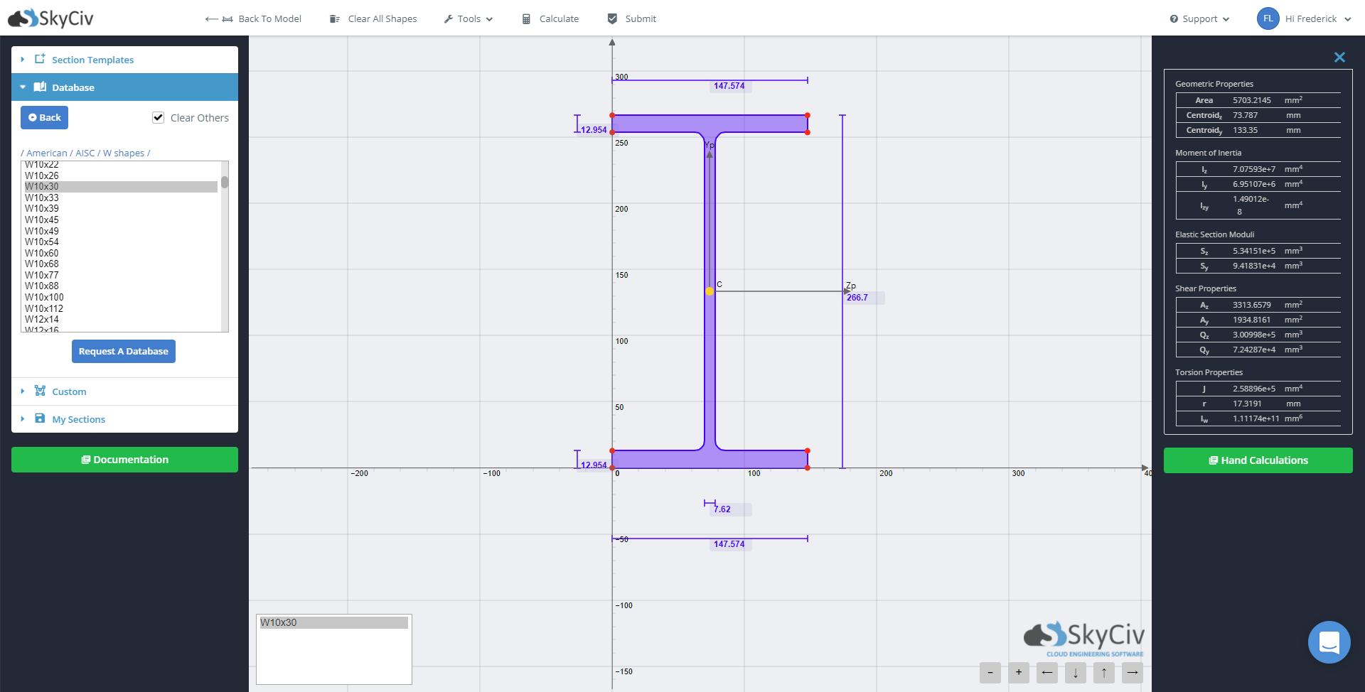
If you wish to know the geometric properties of the section, you click on the ‘Calculate’ button located on the upper menu bar.
Once everything is done, you can submit the section back your beam in SkyCiv Beam.
We will now add the supports for our beam using the ‘Add Support’ button. The program allows for three types of supports: pinned support, roller support, and fixed support. As the conditions for this case is simply supported, we will add a pin and roller supports at both edges of the beam. In this case, we want to add the pin support at x = 0 and the roller support at x = 6.
We then introduce a 10 kN/m distributed load on the entirety of the span using the ‘Add Distributed Load’ button.
The final model should look like this.
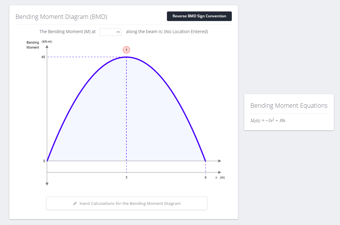
Once everything is done, we can finally solve the beam. Click the ‘Solve’ button on the right hand side of the top menu bar. This will bring you to the Analysis page, which should have results presented in easy-to-understand graphs. The analysis also provides hand calculations if you wish to verify the results manually.
In real applications, simply supported beams may sound relatively basic for a structural engineer, but it is because of its simplicity that design sections are assumed using a simply supported beam. Typically, simply supported beams offer the highest loads and are therefore the most conservative, which is very useful in choosing the right design sections. Examples of real life structures that are modelled as simply supported are one-span bridges.
Indeterminacy is a situation where a structure cannot be solved with the basic equilibrium equations as there are too many indeterminate variables. The number of indeterminate variables is called the degree of indeterminacy. In the situation where more complex analysis is required, a beam analyzer, such as SkyCiv Beam, would be very useful.
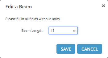
A common example of an indeterminate beam is a continuous beam. In this scenario, we will simulate a three span steel girder. Continuing off from the previous exercise, adjust the length of the beam via the table underneath the diagram. On the table, look for the column ‘Edit/Delete’ and click on the pencil icon  . We then adjust the beam from 6 meters to 18 meters.
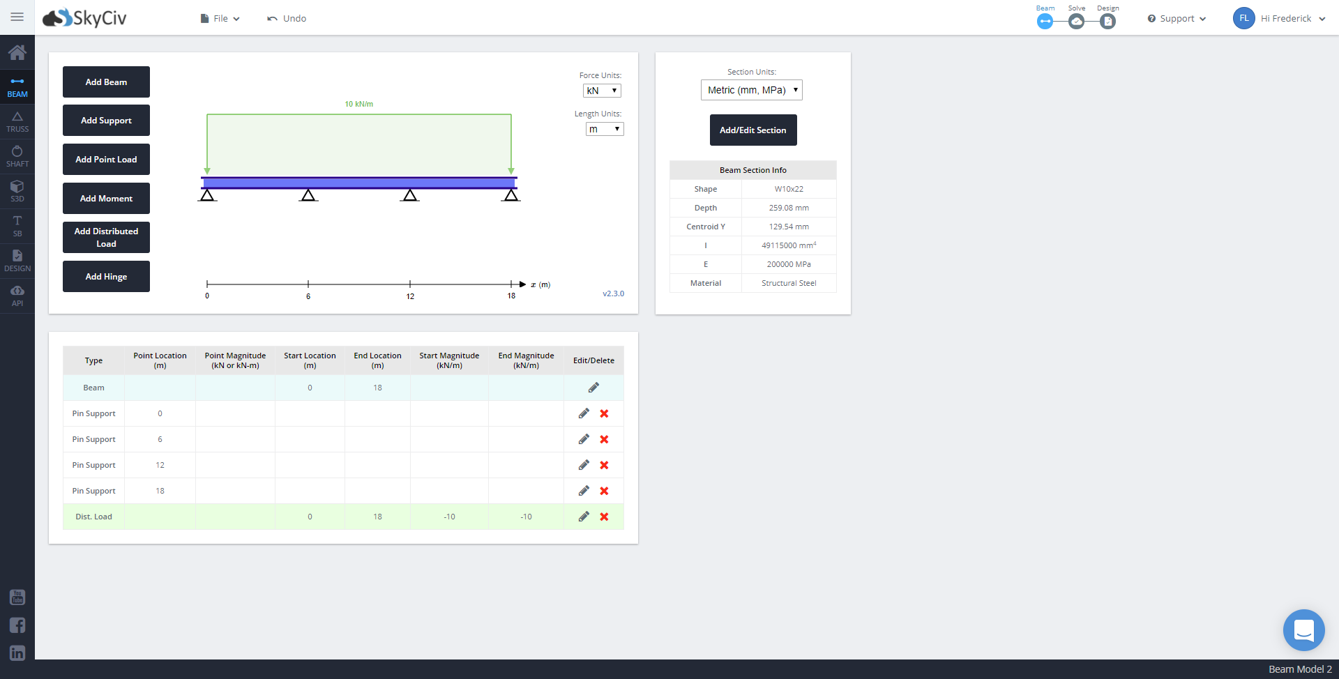
We add two more pinned supports at x = 12 and x = 18. Finally, we adjust the distributed load to cover the entire 18 meter span.
Again, once everything is complete, we can finally solve the beam. When it comes to manually solving indeterminate beams, it is very important to determine the moments at the support reaction as these will allow us to solve for the reactions. Two popular ways of solving continuous beams are by the three-moment equation and moment distribution method.
The Section Builder is a very powerful tool that is integrated to our SkyCiv programs. It also has its standalone launcher, which can be used to create sections. The Section Builder is a program that contains a list of standard sections we can use as design sections for SkyCiv Beam or Structural 3D. It allows us to create custom sections.
In this exercise, we will be using the Section Builder extensively. Previously, we have used the Section Builder to get AISC Wide Flange sections. In this case, we will be making our own section.
Let us go back to the beam previously done for exercise 2. Adjust the supports of the beam such that the pinned supports are now at x = 0, x = 3, x = 6 and x = 9. Similarly, adjust the distributed loading to 9 meters and reduce the magnitude of the load to 1 kN/m. We can then adjust the length of the beam to 9 meters.
Once the beam is complete, we can now go to the Section Builder. Open ‘Section Template’ and choose ‘Lipped Channel’. Apply the following dimensions: h = 100 mm, TFw = 50 mm, TFt = 2 mm, BFw = 50 mm, BFt = 2 mm, Wt = 2 mm, d = 15 mm, r = 4 mm. For general properties, we will use A36 steel properties: E = 200,000 MPa, Fy = 248 MPa, Fu = 400 MPa. We can also apply rotational and translational displacements, as well as mirror the section. In this situation, however, we will not use these changes as the SkyCiv Beam cannot as of yet design with rotated sections. In a situation where there is a rotated section, it is best to break our loadings into components and create two instances of the beam where the local component forces are applied with respect to the major and minor axis of the section.
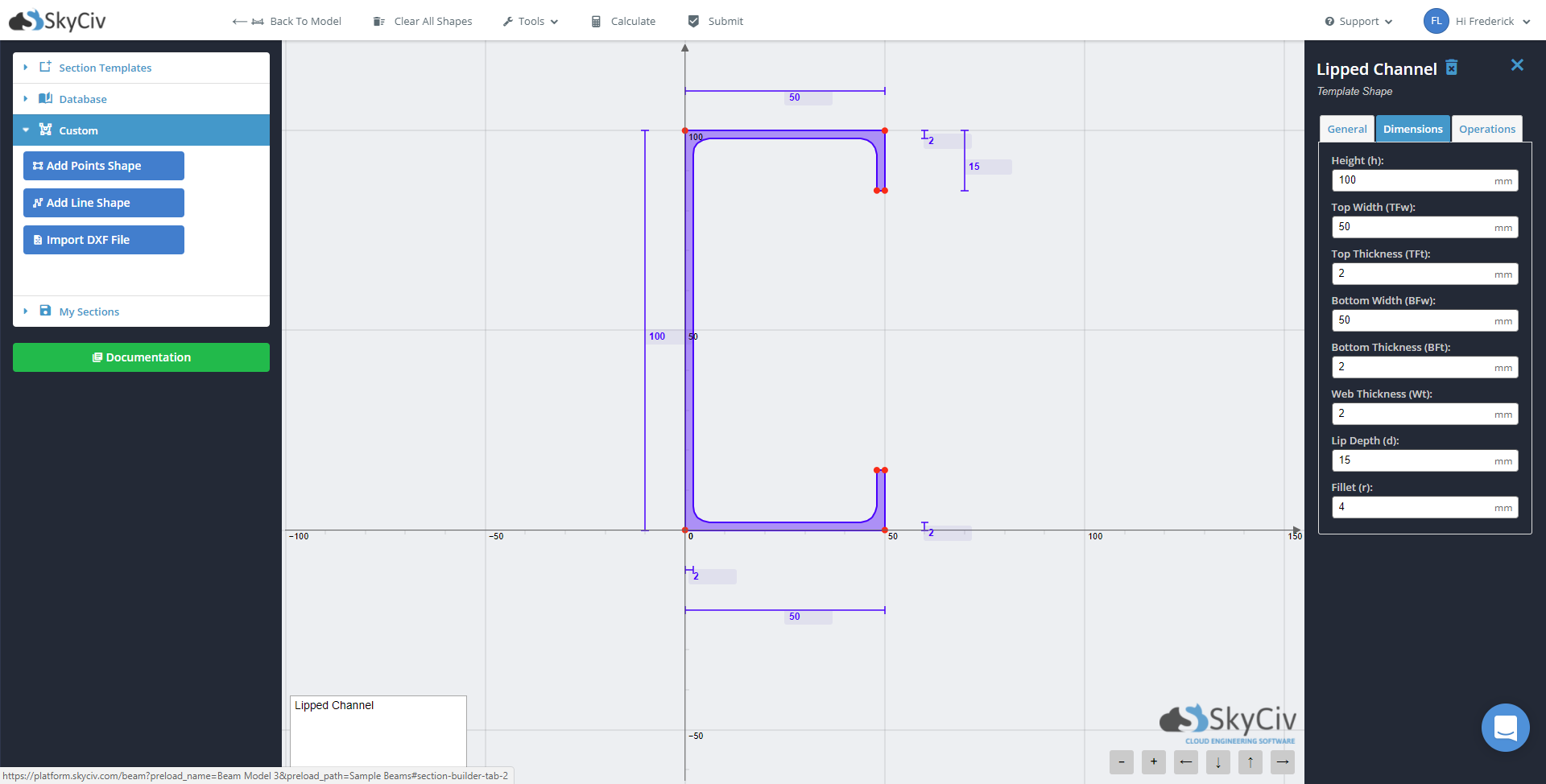
We can now submit this section and solve the beam.

Lipped channels are most often used as floor joist or roof purlins. Typically, they are spaced at 300mm per joist and are usually of light gauge.
Hinges are similar to pinned supports in such a way that they release moments within a member. This is very important for heavily loaded structures as they can lead to a member failing in the design stage. It can also pass these loads into other members, which can increase the design requirement of the structure. In such a scenario, a hinge within the member can release these internal stresses and lower the design requirement of the structure.
In this situation, we will create a beam with the following properties:
Finally, we will introduce random loadings to familiarize ourselves with the other loading types. Add a trapezoidal loading between x = 0 with a magnitude of -2 kN/m and x = 3 with a magnitude of -4 kN/m. Add a 2 kN point load at x = 4.5 and another point load of 3 kN with an angle of 60 degrees with respect to the positive x-axis at x = 7.5. Finally, add a 1 kN-m moment at x = 4.
SkyCiv Beam is a very powerful and simple tool for beam analysis and design. Anything more complex, such as a truss, requires the use of a structural analysis software, such as Structural 3D.
Trusses are structures that are connected typically by pinned joints. As the joints are pinned, the only force being carried internally are axial loads.
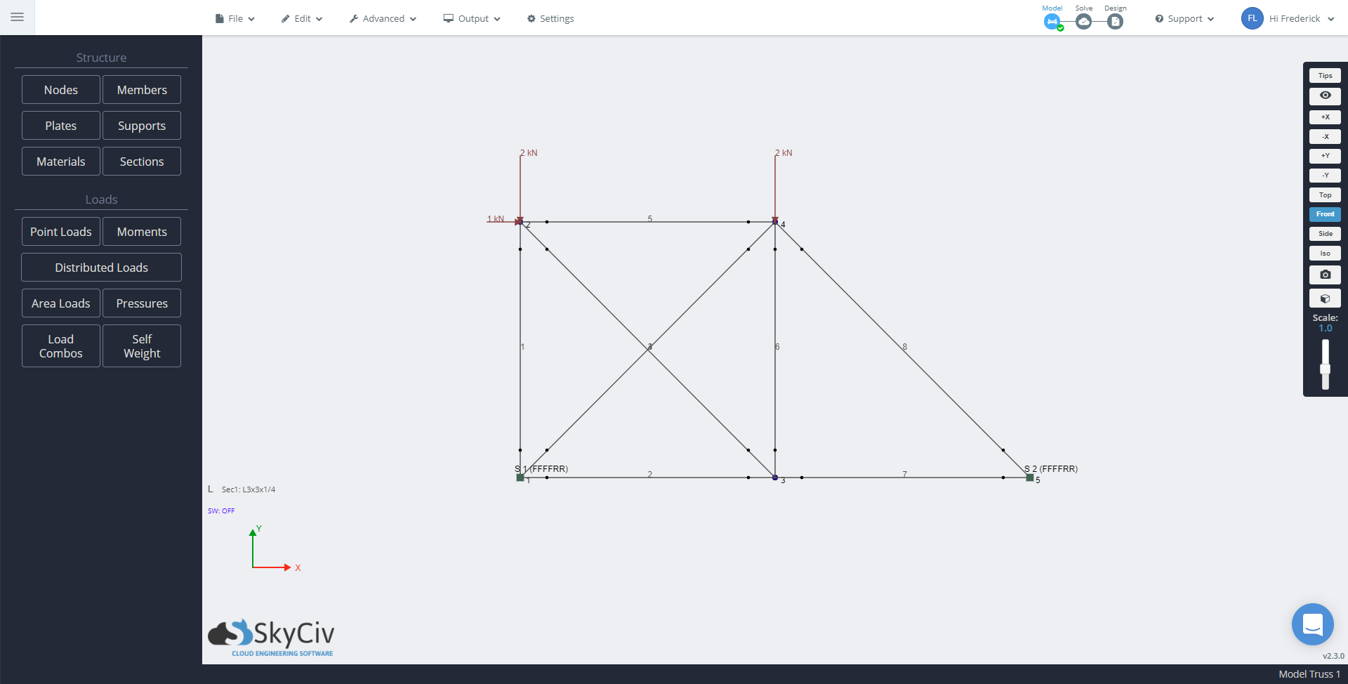
In this section, we will create an 8 member truss. We need open structural 3D first. We will then be greeted with the interface below.

On the left side of the interface, click the ‘Nodes’ tab. Input the following nodes one-by-one, clicking ‘Apply’ after placing each node.
One thing to note here is that the z coordinate is set to zero as the structure we will be doing is a two-dimensional.
Click the ‘Members’ tab. Enable Advanced options as we will also include the section’s angle of rotation Input the following members one-by-one. Click ‘Apply’ after placing each node.
Do note that the arrangement of the nodes is important, where Node A is the starting node and Node B is the ending node.
We will add pinned supports at Node 1 and Node 5 via the ‘Support’ tab. Similarly, click on the ‘Point Loads’ tab. We will apply point loads on the nodes below.
In this situation, we will not go to the ‘Materials’ tab and use the default value that the program has assigned to us, which is steel. Finally, we go to the ‘Sections’ tab and import an L3x3x1/4 angle bar (This located at the Database > American > AISC > Equal angles). Once the model is complete, we can solve the structure.
The Datasheet is a useful feature that allows you to view a collection of structural elements into a spreadsheet. It basically allows you to input all the data required at once or as you go along. In Structural 3D, every aspect of the model creation can be done via the Datasheet feature.
In this exercise, we will replicate the previous truss using the datasheet. Click the Advanced tab at the top menu bar and click Datasheet entry. Select ‘Nodes’ to open the Nodes datasheet icon  .Fill out the datasheet such that the table will look like this:
| ID | X Position (m) | Y Position (m) | Z Position (m) |
|---|---|---|---|
| 1 | 0 | 0 | 0 |
| 2 | 0 | 2.5 | 0 |
| 3 | 2.5 | 0 | 0 |
| 4 | 2.5 | 2.5 | 0 |
| 5 | 5 | 0 | 0 |
For the Members, the datasheet should look like this.
| ID | Node A | Node B | Type | Section ID | Rotation (deg) | A Fixity | B Fixity | Offsets A (mm) | Offsets B (mm) | Cable Length (m) |
|---|---|---|---|---|---|---|---|---|---|---|
| 1 | 1 | 2 | Continuous | 1 | 90 | FFFFRR | FFFFRR | 0,0,0 | 0,0,0 | - |
| 2 | 1 | 3 | Continuous | 1 | 0 | FFFFRR | FFFFRR | 0,0,0 | 0,0,0 | - |
| 3 | 1 | 4 | Continuous | 1 | 90 | FFFFRR | FFFFRR | 0,0,0 | 0,0,0 | - |
| 4 | 2 | 3 | Continuous | 1 | 90 | FFFFRR | FFFFRR | 0,0,0 | 0,0,0 | - |
| 5 | 2 | 4 | Continuous | 1 | 90 | FFFFRR | FFFFRR | 0,0,0 | 0,0,0 | - |
| 6 | 3 | 4 | Continuous | 1 | 0 | FFFFRR | FFFFRR | 0,0,0 | 0,0,0 | - |
| 7 | 3 | 5 | Continuous | 1 | 0 | FFFFRR | FFFFRR | 0,0,0 | 0,0,0 | - |
| 8 | 4 | 5 | Continuous | 1 | 90 | FFFFRR | FFFFRR | 0,0,0 | 0,0,0 | - |
Note that in cases where a column has repeating data, you can highlight adjacent rows that have repeating data, then click and drag the box located at the bottom-right corner of your highlighted rows. In this case, columns that have repeating data are the Type, Section ID, A Fixity, B Fixity, Offsets A, and Offsets B. Cable length is left blank.
Some additional things to note, Fixity refers to the description of a release of a joint. In this case, the nodes a pinned so the moments are released. SkyCiv’s code for pinned joints is FFFFRR. Offsets refers to a member’s displacement from node center to node center. The offsets are visible when we use the 3D Renderer.
Going through the ‘Support’ tab, we will introduce the pinned supports into our model.
| ID | Node ID | Restraint Code | TX Stiffness (kN/m) | TY Stiffness (kN/m) | TZ Stiffness (kN/m) | RX Stiffness (kNm/rad) | RY Stiffness (kNm/rad) | RZ Stiffness (kNm/rad) |
|---|---|---|---|---|---|---|---|---|
| 1 | 1 | FFFFRR | 0 | 0 | 0 | 0 | 0 | 0 |
| 2 | 5 | FFFFRR | 0 | 0 | 0 | 0 | 0 | 0 |
When it comes to assigning the type of restraint, we type the restraint code that we want in our model. The restraint code is available at the prior page where the code is displayed for each restraint type. In this case, the code for a pinned support is FFFFRR.
| ID | Apply To | Node ID | Member ID | Position (%) | X Mag (kN) | Y Mag (kN) | Z Mag (kN) | Load Group |
|---|---|---|---|---|---|---|---|---|
| 1 | Node | 2 | - | - | 1 | 0 | 0 | LG |
| 2 | Node | 2 | - | - | 0 | -2 | 0 | LG |
| 3 | Node | 4 | - | - | 0 | -2 | 0 | LG |
For point loads, while they are typically placed on joints, Structural 3D allows you to place loads within the member as well. Simply select ‘Member’ located at the ‘Apply To’ Column. The Load Group will be left default at LG.
Similar to the previous exercise, we will leave the Materials as is as the default material that Structural 3D assigns is steel. For our sections, we will use the builder and import our L3x3x1/4 angle bar. The model should be similar now to our previous truss.
Unlike a truss, which transfer only axial loads within its members, frames transfer shear and moment. Technically, a truss with fixed joints is a frame. As trusses can only carry axial forces, external loads are only applied at the joints, whereas, loads can be applied anywhere on the frame. Naturally, frames are more complex because of this.
In this exercise, we will be making a two-dimensional two-storey frame. The data displayed below are displayed in a datasheet format, although you need not exclusively use the datasheet for this exercise.
| ID | X Position (m) | Y Position (m) | Z Position (m) |
|---|---|---|---|
| 1 | 0 | 0 | 0 |
| 2 | 4 | 0 | 0 |
| 3 | 0 | 3 | 0 |
| 4 | 4 | 3 | 0 |
| 5 | 0 | 6 | 0 |
| 6 | 4 | 6 | 0 |
| ID | Node A | Node B | Type | Section ID | Rotation (deg) | A Fixity | B Fixity | Offsets A (mm) | Offsets B (mm) | Cable Length (m) |
|---|---|---|---|---|---|---|---|---|---|---|
| 1 | 1 | 3 | Continuous | 1 | 0 | FFFFRR | FFFFRR | 0,0,0 | 0,0,0 | - |
| 2 | 2 | 4 | Continuous | 1 | 0 | FFFFRR | FFFFRR | 0,0,0 | 0,0,0 | - |
| 3 | 3 | 4 | Continuous | 1 | 0 | FFFFRR | FFFFRR | 0,0,0 | 0,0,0 | - |
| 4 | 3 | 5 | Continuous | 1 | 0 | FFFFRR | FFFFRR | 0,0,0 | 0,0,0 | - |
| 5 | 4 | 6 | Continuous | 1 | 0 | FFFFRR | FFFFRR | 0,0,0 | 0,0,0 | - |
| 6 | 5 | 6 | Continuous | 1 | 0 | FFFFRR | FFFFRR | 0,0,0 | 0,0,0 | - |
| ID | Node ID | Restraint Code | TX Stiffness (kN/m) | TY Stiffness (kN/m) | TZ Stiffness (kN/m) | RX Stiffness (kNm/rad) | RY Stiffness (kNm/rad) | RZ Stiffness (kNm/rad) |
|---|---|---|---|---|---|---|---|---|
| 1 | 1 | FFFFFF | 0 | 0 | 0 | 0 | 0 | 0 |
| 2 | 2 | FFFFFF | 0 | 0 | 0 | 0 | 0 | 0 |
| ID | Member ID | Axes | Start X (kN/m) | End X (kN/m) | Start Y (kN/m) | End Y (kN/m) | Start Z (kN/m) | End Z (kN/m) | Start Pos (%) | End Pos (%) | Load Group |
|---|---|---|---|---|---|---|---|---|---|---|---|
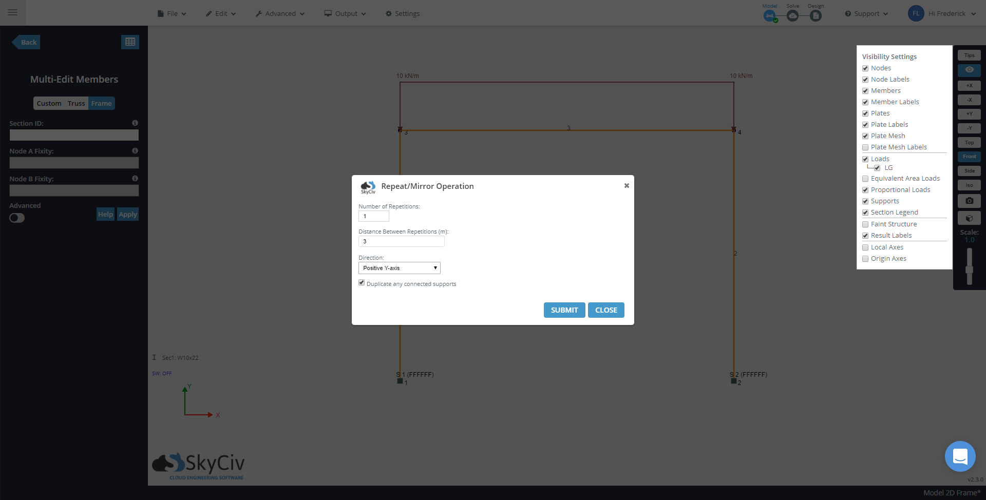
| 1 | 3 | Global | 0 | 0 | -10 | -10 | 0 | 0 | 0 | 100 | LG |
| 2 | 6 | Global | 0 | 0 | -10 | -10 | 0 | 0 | 0 | 100 | LG |
Again, the section we will use is the W10x22 section from the Section Builder.
Structural 3D analyzes plates through meshing, which is a technique of analysing a plate by breaking it into smaller elements, usually squares or triangles. Without meshing, Structural 3D would analyze the plate as a whole, which can lead to inaccurate results, although Structural 3D prevents structural analysis from the beginning if the plates are not meshed.
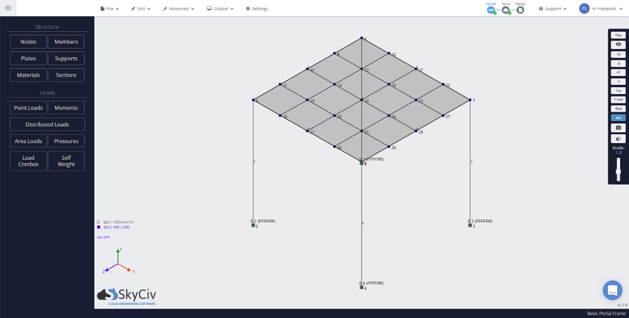
In this exercise, we will model a basic three-dimensional portal frame with a plate on top. For relative convenience, we will present the needed data with datasheets.
| ID | X Position (m) | Y Position (m) | Z Position (m) |
|---|---|---|---|
| 1 | 0 | 0 | 0 |
| 2 | 0 | 0 | 3 |
| 3 | 3 | 0 | 0 |
| 4 | 3 | 0 | 3 |
| 5 | 0 | 3 | 0 |
| 6 | 0 | 3 | 3 |
| 7 | 3 | 3 | 0 |
| 8 | 3 | 3 | 3 |
| ID | Node A | Node B | Type | Section ID | Rotation (deg) | A Fixity | B Fixity | Offsets A (mm) | Offsets B (mm) | Cable Length (m) |
|---|---|---|---|---|---|---|---|---|---|---|
| 1 | 1 | 5 | Continuous | 1 | 0 | FFFFRR | FFFFRR | 0,0,0 | 0,0,0 | - |
| 2 | 2 | 6 | Continuous | 1 | 0 | FFFFRR | FFFFRR | 0,0,0 | 0,0,0 | - |
| 3 | 3 | 7 | Continuous | 1 | 0 | FFFFRR | FFFFRR | 0,0,0 | 0,0,0 | - |
| 4 | 4 | 8 | Continuous | 1 | 0 | FFFFRR | FFFFRR | 0,0,0 | 0,0,0 | - |
| 5 | 5 | 6 | Continuous | 1 | 0 | FFFFRR | FFFFRR | 0,0,0 | 0,0,0 | - |
| 6 | 5 | 7 | Continuous | 1 | 0 | FFFFRR | FFFFRR | 0,0,0 | 0,0,0 | - |
| 7 | 6 | 8 | Continuous | 1 | 0 | FFFFRR | FFFFRR | 0,0,0 | 0,0,0 | - |
| 8 | 7 | 8 | Continuous | 1 | 0 | FFFFRR | FFFFRR | 0,0,0 | 0,0,0 | - |
| ID | Nodes | Thickness (mm) | Material ID | Rotation (deg) | Type | Offset (mm) | State |
|---|---|---|---|---|---|---|---|
| 1 | 5,6,8,7 | 50 | 1 | 0 | Mindlin | 0 | Plane Stress |
To apply plates into the model, you need to include all the nodes that you want to include in your plate and arrange them in such a way that the nodes are adjacent to each other. A plate containing nodes 5,6,8,7 will look different to a plate with nodes arranged 5,6,7,8. The below image is what the structure will look like if the nodes of the plate are arranged 5,6,7,8. Note: This would be the incorrect way to model a plate.
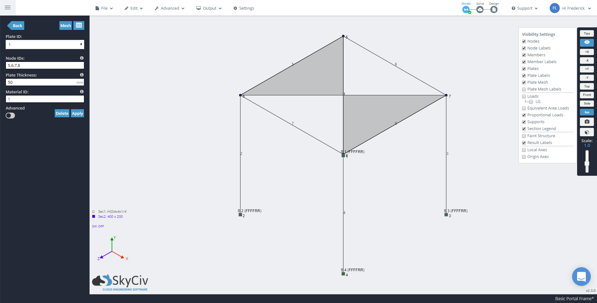
Once you have modelled your plate correctly, you can mes by right clicking -> Mesh Plate, or by selecting the plate and going Advanced -> Plate Mesher. Experiment with the different meshes, but as a simple case your mesh should look something like this under Structured Quads:
| ID | Node ID | Restraint Code | TX Stiffness (kN/m) | TY Stiffness (kN/m) | TZ Stiffness (kN/m) | RX Stiffness (kNm/rad) | RY Stiffness (kNm/rad) | RZ Stiffness (kNm/rad) |
|---|---|---|---|---|---|---|---|---|
| 1 | 1 | FFFFRR | 0 | 0 | 0 | 0 | 0 | 0 |
| 2 | 2 | FFFFRR | 0 | 0 | 0 | 0 | 0 | 0 |
| 3 | 3 | FFFFRR | 0 | 0 | 0 | 0 | 0 | 0 |
| 4 | 4 | FFFFRR | 0 | 0 | 0 | 0 | 0 | 0 |
| ID | Type | Node IDs | Member IDs | Magnitude (kPa) | Direction | Load Group |
|---|---|---|---|---|---|---|
| 1 | Two-Way | 5,6,8,7 | - | -2 | Global Y | LG |
Note that you can also use Pressures aside from Area Loads. Similarly, apply the same procedure for creating plates to Area loads/Pressure loads.
Finally, for our section, we will be using an HSS4x4x1/4 cross section from the Section Builder (Database > American > AISC > Square HSS)
Most often, structures composed of more than one type of section. It would be economically impractical to make use of a single section that would be used in the entirety of the structure.
That will be the case that we will apply in this situation. In this exercise, we will model a two-dimensional roof frame. Typically, two-dimensional roof frames are aligned and spaced several meters apart from each other to carry loads from the roof.
| ID | X Position (m) | Y Position (m) | Z Position (m) |
|---|---|---|---|
| 1 | -1 | 0.25 | 0 |
| 2 | 0 | 0 | 0 |
| 3 | 0 | 1 | 0 |
| 4 | 3 | 3.25 | 0 |
| 5 | 4 | 4 | 0 |
| 6 | 9 | 0.25 | 0 |
| 7 | 8 | 0 | 0 |
| 8 | 8 | 1 | 0 |
| 9 | 5 | 3.25 | 0 |
| ID | Node A | Node B | Type | Section ID | Rotation (deg) | A Fixity | B Fixity | Offsets A (mm) | Offsets B (mm) | Cable Length (m) |
|---|---|---|---|---|---|---|---|---|---|---|
| 1 | 1 | 3 | Continuous | 1 | 0 | FFFFRR | FFFFRR | 0,0,0 | 0,0,0 | - |
| 2 | 2 | 3 | Continuous | 2 | 0 | FFFFRR | FFFFRR | 0,0,0 | 0,0,0 | - |
| 3 | 4 | 9 | Continuous | 1 | 0 | FFFFRR | FFFFRR | 0,0,0 | 0,0,0 | - |
| 4 | 4 | 9 | Continuous | 3 | 0 | FFFFRR | FFFFRR | 0,0,0 | 0,0,0 | - |
| 5 | 6 | 8 | Continuous | 1 | 0 | FFFFRR | FFFFRR | 0,0,0 | 0,0,0 | - |
| 6 | 7 | 8 | Continuous | 2 | 0 | FFFFRR | FFFFRR | 0,0,0 | 0,0,0 | - |
| 7 | 8 | 5 | Continuous | 1 | 0 | FFFFRR | FFFFRR | 0,0,0 | 0,0,0 | - |
Note that the beam 4 is connected to beam 3 and beam 7. Beam 3 and 7 are continuous members
| ID | Node ID | Restraint Code | TX Stiffness (kN/m) | TY Stiffness (kN/m) | TZ Stiffness (kN/m) | RX Stiffness (kNm/rad) | RY Stiffness (kNm/rad) | RZ Stiffness (kNm/rad) |
|---|---|---|---|---|---|---|---|---|
| 1 | 2 | FFFFRR | 0 | 0 | 0 | 0 | 0 | 0 |
| 2 | 7 | RFFFRR | 0 | 0 | 0 | 0 | 0 | 0 |
Note that Node 1 is a pinned support while Node 2 is a roller support. As such, not only moments are released at the reactions, but also lateral forces as well. Roof frames with such support configuration have members that are more critically loaded than if both supports are pinned or fixed. However, this can be advantageous as the forces or moments are not transmitted below. Roof frames normally have their supports by beams or columns and transferring these loads may make these structural elements more critically loaded.
For the sections, we will be using W6x9, W8x24 and W8x31 sections from the Section Builder.
Three-dimensional frames are perhaps the most challenging structure a structural engineer can have. As frame joints allows for six degrees of freedom, forces and moments are being applied from all three axes. Solving a frame manually or even with the use of spreadsheet programs can be a tedious process. It is no surprise that complex structures are analyzed with structural analysis software, such as Structural 3D.
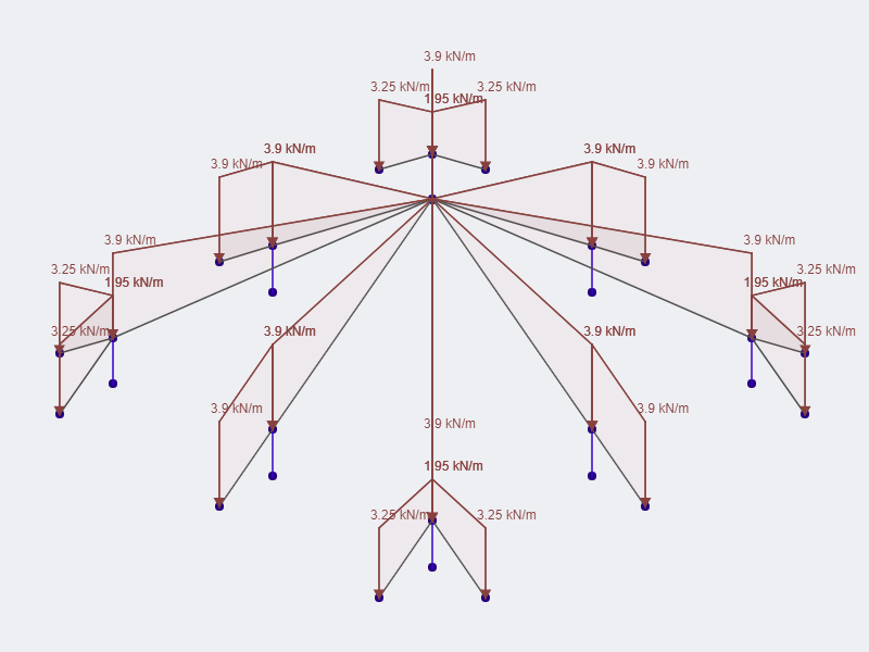
In this last exercise, we will be making a three-dimensional roof frame as shown below. As you have passed through exercise 1-9, we will not provide a datasheet in this course as we will expect that you will be able to do this on your own.
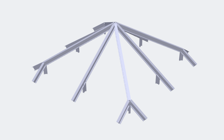
The framing has the following properties:
The loadings will be such that a uniform downward pressure of -1.3 kPa has been imposed upon the structure. Assuming the load is distributed evenly by the purlins (not simulated) to the rafter, the loading should look like the one below.