今天我们将探索如何使用 SkyCiv Structural 3D 中的壳单元对钢支架进行建模:
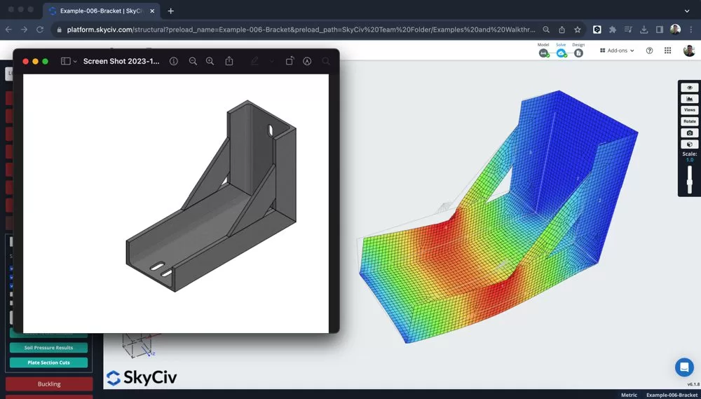
用板构建支架/连接器模型
首先将单位更改为 毫米 因为结构将是一个更小的组件, 所以这个单位系统会更容易使用. 然后我们可以开始放入不同板的边界框, 在教程的这一部分中, 我使用了以下功能:
- 输入算术 – 在输入中使用表达式, 如 450/22.5 自动计算该值
- 笔工具 – 捕捉到 10mm 并关闭连接部件, 我可以很容易地绘制节点来创建第一个板元素的边界框
- 突出显示我的盒子的节点 – 右键点击 – 添加盘子
- 添加一些支撑
支架现在已形成二维形状:
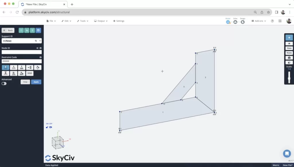
模型建立后,向其中一个节点施加一个小点载荷. 这是为了计算一些早期结果, 但本教程稍后将更详细地探讨加载.
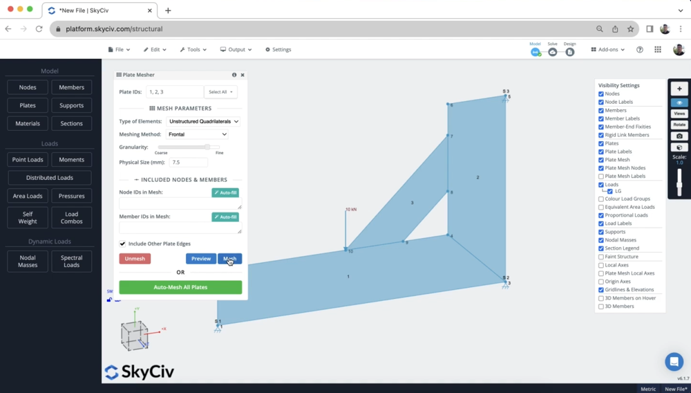
网格化你的盘子
网格划分过程是支架建模中极其重要的部分. 网格的质量和元素之间的连接性将直接影响结果的质量.
粒度发挥作用, 但更重要的是确保您的元件正确连接很重要 按节点. 这确保了板都沿其边缘连接. 为了确保这一点, 我们建议使用 网格全部 或同时对所有板进行网格划分, 使用网格工具. 您可以通过选择您想要网格化的板来访问它 (或按 CTRL 键 + 一个) 然后右键单击 – 网板:
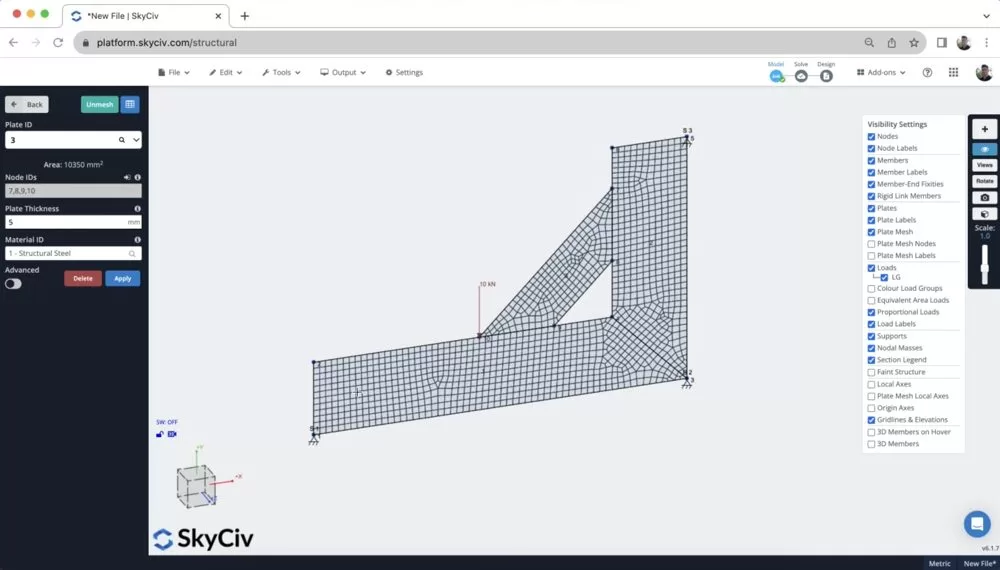
After meshing, it’s a good idea to inspect the mesh to ensure all plates are connected by adjacent nodes:
Reviewing some Results
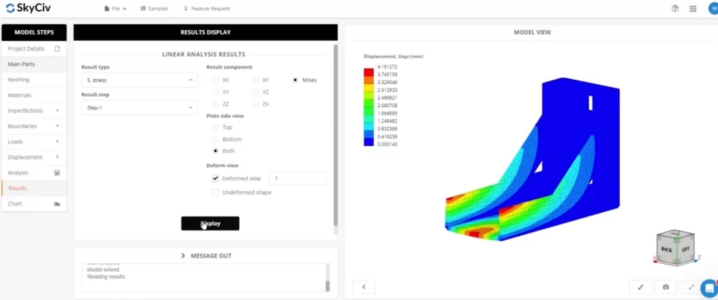
Once we have the model built, loaded, supported and meshed, we can run a quick analysis to get some results. After running a Static Analysis, I then selected the results for 通过米塞斯 under the red 板块 button on the left panel. There are a number of different plate results (主要/次要主应力, 膜, 剪切等…), 有关不同的更多信息 我们支持的壳单元结果. 但现在, 我们可以回顾一下 通过米塞斯 结果:
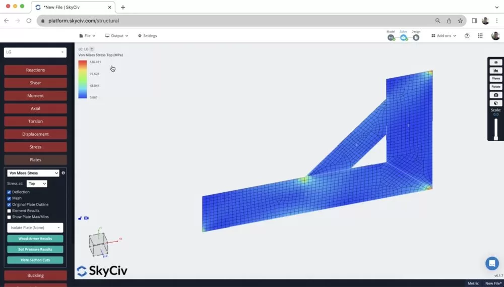
从这里可以看出,支撑处和点载荷的位置有非常高的集中载荷. 注意到这一点很重要,因为我们将探索如何提高该模型的质量 – 使其更加贴近生活 (since loads are rarely concentrated at such a finite location).
It’s also helpful here to animate the displacement (现在点击其中一位成员 小号 and scroll your mouse) to make sure the bracket is deflecting in a way you’d expect it to. It’s also helpful to do a bite of a review in 2D before building your model out in 3D to save yourself time.
Distributing your Point Load using Rigid Links
One of the issues is that the point load is concentrated at a single point, which is rarely the case.
所以, 您可以将负载分成更小的组件, 或使用 刚性连接 将力分配到多个节点. 我们将使用第二种策略, 所以我们只有一个单点负载,这将使未来的修改变得更加容易.
通过在要连接的节点之间单击并拖动. 注意: 当这样做时, 拖 从 将点载荷节点连接到网格节点,以确保点载荷节点始终是 主节点.
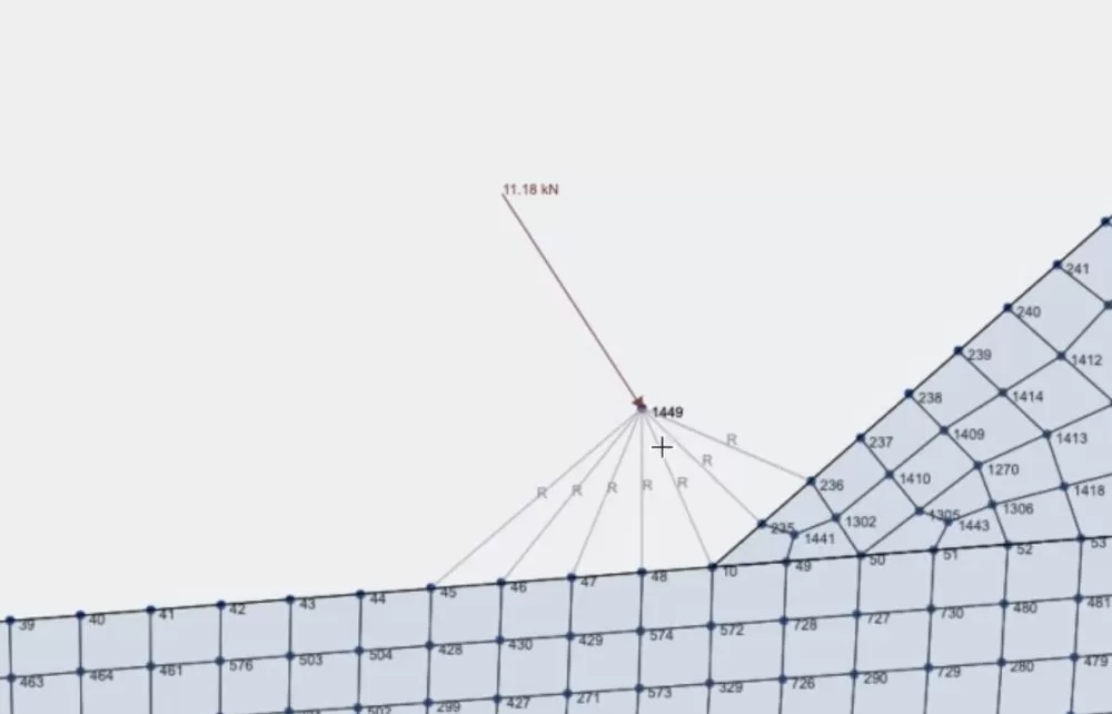
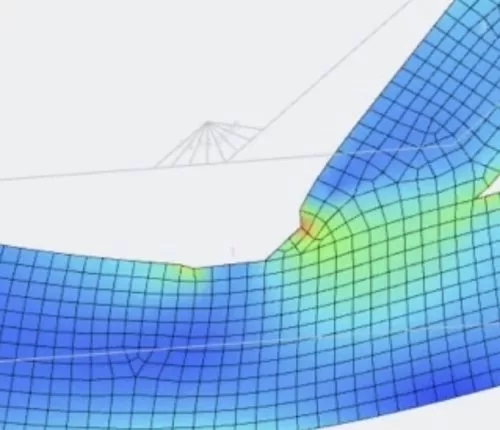
这也导致了点载荷的更准确和更好的分布. The stress has gone from approx. 100MPa to around 50MPa:
构建 3D 模型
Once we’re happy with our 2D results, now is a good idea to build out the model in 3D. 这样做, we are making the most out of these modelling functions:
1. 复制和粘贴 – Copying the entire model (CTRL键 + 一个) 然后 (CTRL键 + C). When I go to paste (CTRL键 + V) it will ask me to select a reference node. I used a reference node of 0,0,200 so it pasted the second bracket 200mm along the z axis:
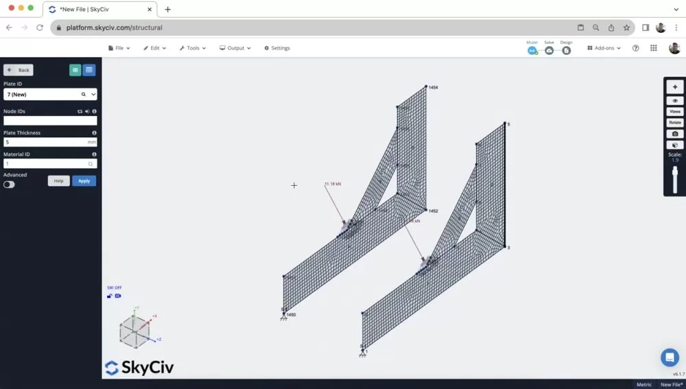
2. 右键点击 – 添加盘子 – I then just added plates (the same way I did in step 1), using CTRL + drag to select the 4 角节点,然后右键单击 添加盘子. 重新网格化后, 现在我们的模型已经完成了:
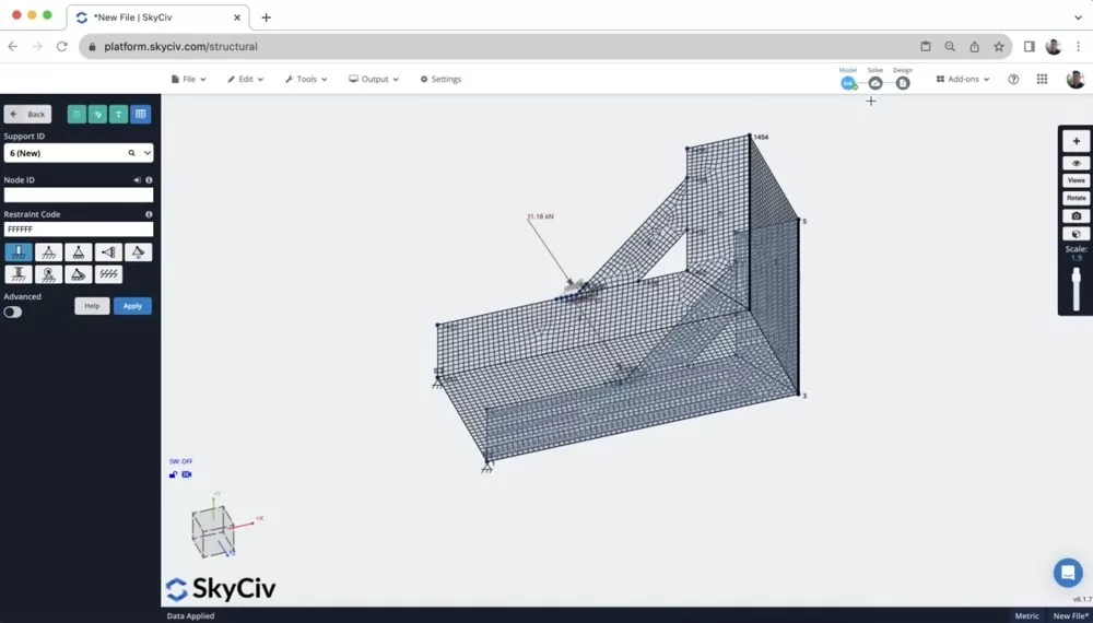
3. 添加其他零件 – 本教程中未介绍, 但您也可以使用类似功能 孔切口 和 弯曲元件 对于更复杂形状的板材. 注意: 这通常是在啮合前完成的.
[奖金] 在 SkyCiv FEA 中对此结构进行建模
- 导入DXF – 您可以首先导入要拉伸的横截面的 DXF
- 添加板属性 – 分配板厚, 模型的切口和任何其他方面
- 添加边缘 – 添加括号的外边缘
- 施加载荷和支撑 – 单点载荷可以施加到一组节点, 无需刚性构件
常问问题
It’s important to understand the various node properties of a rigid link (注意, these are the same for rigid diaphragms)
- 主节点: The master node is the reference node that controls the behavior of the rigid link. It remains fixed or constrained in some way, and the movement or deformation of this node dictates the behavior of the entire rigid link. The master node is typically associated with the primary structure or component.
- Slave Node(s): The slave nodes are connected to the master node via the rigid link. These nodes mimic the movements and deformations of the master node. 本质上, they are constrained to move exactly as the master node moves. The slave nodes are typically associated with secondary structures or components that are rigidly connected to the primary structure.
It’s important to note that a Master node can not be a slave to another Master. So when setting up your rigid members, it’s important to connect FROM the master to a number of slave nodes i.e. each rigid member should have the same master node.
为您的盘子添加切口, 首先添加节点来勾勒出剪切图所在的位置. 注意, 使用曲线杆件工具在这里通常很有帮助.
然后您可以右键单击该板, 你的剪切节点所在的位置, 然后点击 板开孔
在结构3D中, we currently support 线性分析 只要. SkyCiv Shell FEA 中可使用更高级的分析, 包含:
- 线性的 (静止的)
- 非线性屈曲
- 几何非线性 (静止的)
- 几何的 + 材料非线性 (静止的)
- 几何的 + 材料非线性 (显式的)

