How to Design an AISC Steel Connection in SkyCiv
Learn how to design a steel connection using SkyCiv 结构分析软件 and the integrated Steel Connection Design module.
In this walkthrough we’ll look at modelling a simple frame (with some shortcuts!), reviewing the analysis results and performing some connection design using AISC!
Modelling a Steel Frame
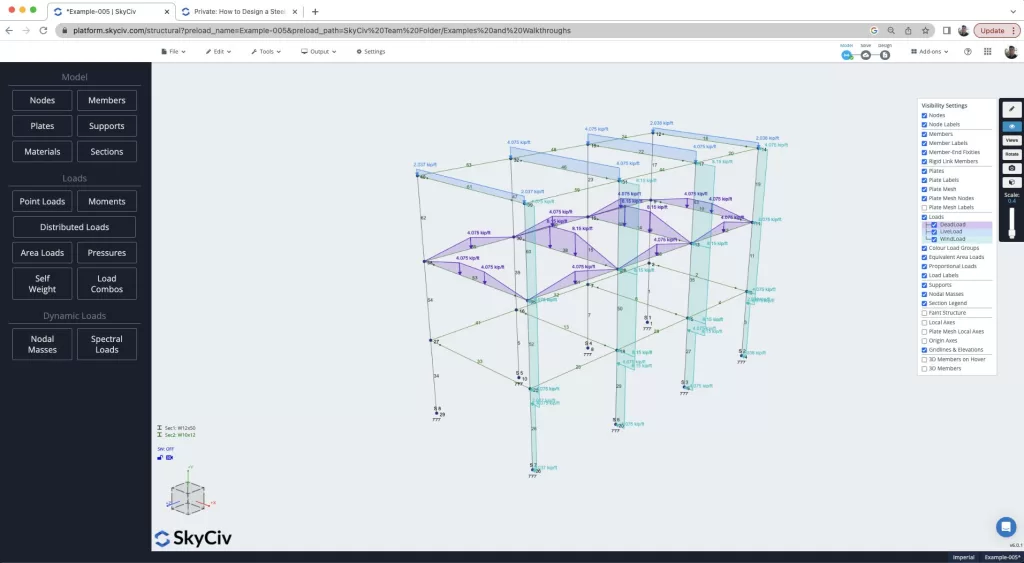
We start this walkthrough by first building a steel frame. If you’re already familiar with this part of the process, feel free to skip through! But we walkthrough how you can build a model like this in a few minutes, using some of the SkyCiv favorite features, 包含:
- 笔工具 – model quickly using the pen tool
- 复制和粘贴 – copy and paste substructures to easily build up your model
- Multi-edit – hold CTRL and drag the mouse to select and multi-edit parts of your model
- Search Sections – quick add sections from our library in seconds, using search
- 区域负荷 – one way, 自动计算的双向和风荷载面积荷载 (并重新调整!) 成员的朝贡地区.
- 设计代码荷载组合 – 进口美国土木工程师协会 7-16 自动加载组合
Reviewing Critical Member Forces
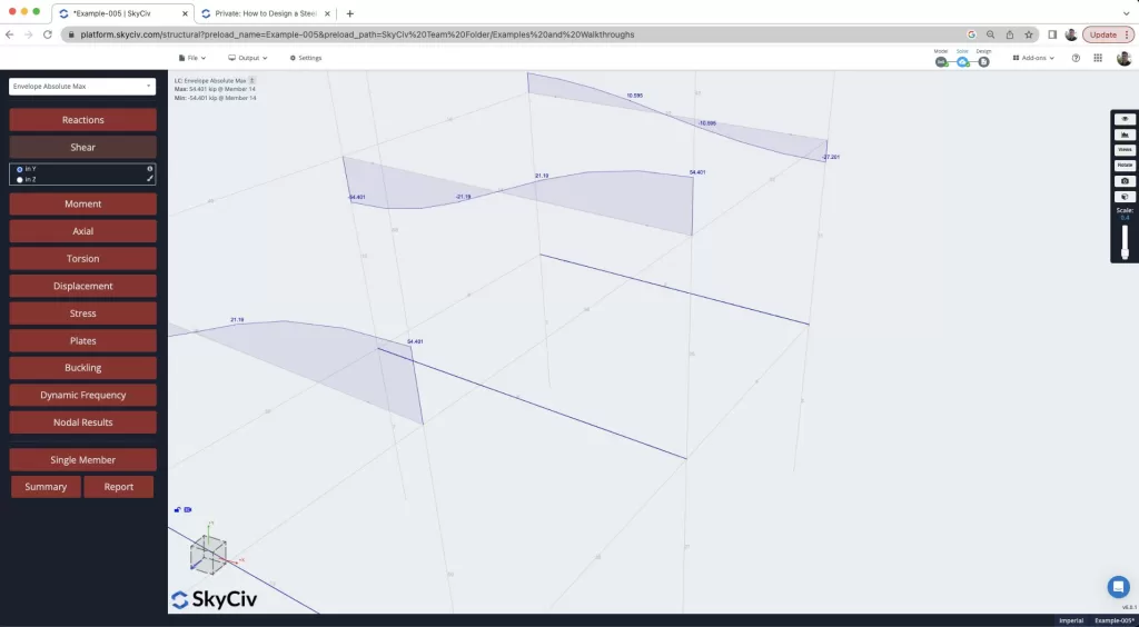
现在我们已经解决了模型, 我们查看分析结果,尝试找到最坏情况下的杆件力,作为我们连接设计的基础. 审查 信封绝对最大值 结果将向我们展示所有载荷组合中最坏情况下的力. 我们还可以使用CTRL + 拖动功能来隔离模型的各个部分. 这非常有帮助,因为我们可以快速查看我们的模型, 找到杆端最坏情况的剪力,如下图所示, 我们看到的成员 14 框架中剪切力最差:
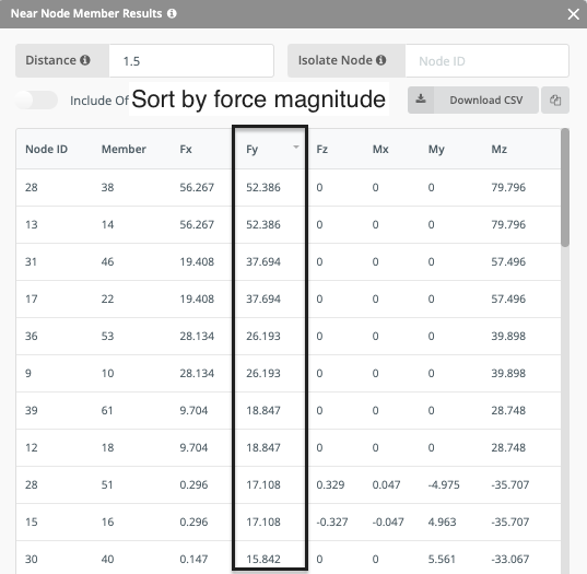
我们可以使用另一个有用的功能来识别这一点, 是个 节点结果. 这在较大的模型中特别有用,您可能无法目视检查和识别最坏情况的结果. Here you can sort the table to make it easy to identify the highest force at a node, as well as it’s connected member. The table sort function is really useful here and can be used to sort the forces based on any force direction, 在这种情况下 飞云:
Designing a Shear Connection
So we’ve identified the worse case connection in our model, now let’s design the connections based on this magnitude. The idea here is that we design them all as one type, 这使得安装和施工更加容易. 所以, 考虑到这一点,我们右键单击选择光束 14 和专栏 35 并打开模块. 很多信息都是从分析模型中提取的, 包含:
- 梁截面属性
- 柱截面属性
- 材料特性
- 设计力量
然后我们开始设计连接组件的过程. 首先选择连接类型 (剪力, 片刻, 轴向等..) 以及设计代码, 在这种情况下,AISC. The software will also warn the user if forces are detected in other directions with a yellow warning:
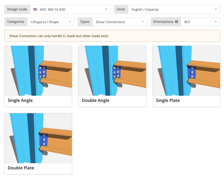
从那里, we would select a connection, in this example we’re going with a double angle connection. 最后, we wish to design the fixtures to both the beam and column:
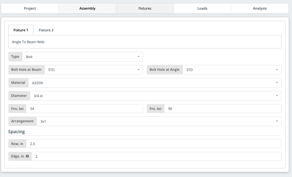
With easily identified input, it takes a couple of minutes to get your design ready. 图形界面可帮助用户识别设计中的问题,同时提供有关您的设计和输入的即时反馈. 完成所需的输入后, 你应该有一个设计就绪的连接:
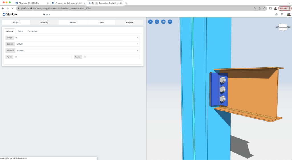
Reviewing the Calculations
现在可以运行设计检查. 结果一目了然, 信息丰富且简洁 – 显示清晰的效用比率, 通过/失败标准的颜色编码:
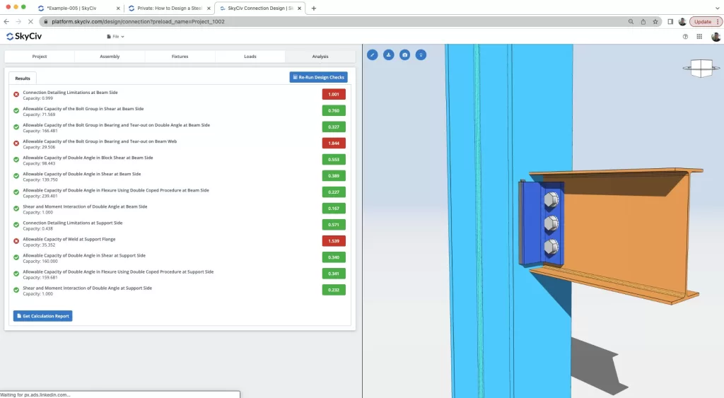
显然正在进行多项检查, 从详细检查, 螺栓检查, 角度检查, 焊接检查, 剪切和弯曲检查仅举几例. 该软件具有强大而清晰的报告功能, 帮助工程师识别设计中的问题并了解如何最好地改进设计:
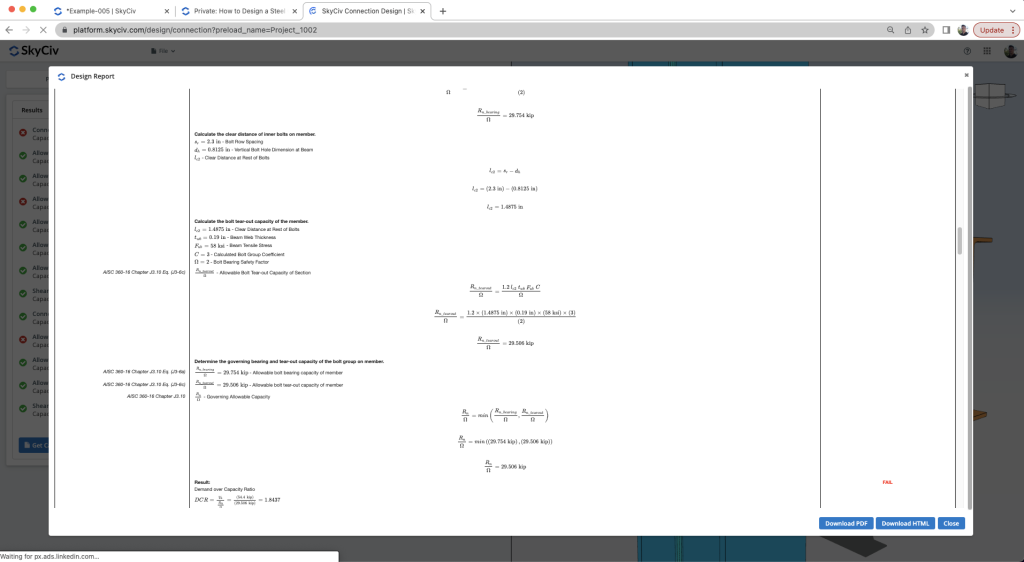
有了这个帮助, 用户获得优化或完成设计所需的所有信息. 在本演练中, 我们演示用户如何查看结果, 改变他们的设计并获得更好的结果.
常问问题
您可以使用横向支撑系统来抵抗横向载荷,使梁仅承受剪切载荷. 如果不, 使用刚性框架将需要您设计具有力矩载荷的连接,这会导致成本更高.
您可以按照上面的建议对结构进行建模,也可以更改梁的固定性. 您还可以尝试将梁尺寸更改为更硬的尺寸,以便梁可以将力矩载荷作为内部载荷来承载.
确保检查成员是否受支持. 我们目前仅支持美国和澳大利亚尺寸,并且仅支持 I 形或 HSS/RHS/SHS 形状. 还要确保它是梁与梁/柱的连接并且彼此完全垂直.
检查计算报告. 每项检查都应该直观地告诉您要更改什么. 如果螺栓检查失败, 您可以更改螺栓直径或螺栓等级,也可以更改螺栓间距. 如果焊接失败, 您可以增加焊缝尺寸或增加连接长度来增加焊缝长度. 如果连接器 (盘子, 角度, 等等) 失败, 增加其厚度或长度. 如果梁或柱失效, 您可以更改 S3D 中的大小或尝试使连接更大.

