Steel Base Plate Design Australian Code Example
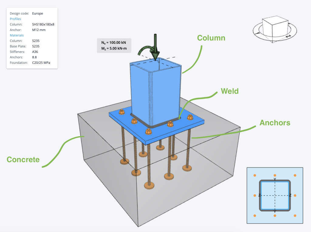
Below is an example of some Australian Base Plate Calculations that are commonly used in base plate design. Often when designing base plates, we will consider a few different checks relating to the various components of a base plate, namely:
- The Concrete base – generally checked against bearing and compression forces in reference to AS3600
- The Welds – welds need to be checked, to ensure they provide adequate restraint and do not fail under stress to AS4100
- Anchor Bolts – can fail due to a number of reasons, as shown below in the example anchor bolt design calculations to AS5216
- Steel Member (Column) checks – usually based on local steel design standards
Currently, the Steel Base Plate Design module implements the following checks below. The paid version of this software, includes detailed step-by-step calculations, so that engineers can review exactly how these calculations are made!
Try this calculation using SkyCiv Free Base Plate Calculator:
Concrete Check
The Steel Base Plate Design checks Concrete Bearing check designed in according to AS3600-2018 and shall satisfy:
- \( \phi \) – 0.6 – Capacity factor
- \( f_{c}^{‘}\) – Concrete compressive strength
- \( A_{1}\) – Base plate area
- \( A_{2}\) – Concrete (pedestal, foundation) area
Try this calculation using SkyCiv Free Base Plate Calculator:
Weld Check
The Steel Base Plate Design checks the weld designed according to AS4100-2021 and shall satisfy:
- \( \phi \) – 0.80 – Resistance factor for welded connections
- \( f_{uw} \) – Nominal tensile strength of weld metal
- \( t_{t} \) – Design throat thickness
- \( v_{w}^{*} \) – Design force per unit length of weld
Try this calculation using SkyCiv Free Base Plate Calculator:
Anchor Bolts Checks
The Steel Base Plate Design check the anchors capacity. Please see below base plate anchor bolt per Australian code:
Bolt in tension
A bolt subject to design tension force is designed according to AS5216:2018 and shall satisfy:
- \( \phi M_{s} \) – Capacity factor for steel in tension. where \( \frac{5 \times f_{yf} }{ 6 \times f_{uf} } \leq \frac{1}{1.4} \)
- \( A_{s} \) – tensile stress area
- \( f_{yf} \) – Minimum yield strength of the bolt
- \( f_{uf} \) – Minimum tensile strength of the bolt
Bolt in shear
A bolt subject to a design shear force is designed according to AS5216:2018 and shall satisfy:
- \( \phi M_{s} \) – Capacity factor for steel in tension. where \( \frac{5 \times f_{yf} }{ 6 \times f_{uf} } \leq \frac{1}{1.4} \)
- \( A_{c} \) – Minor diameter area of the bolts
- \( f_{uf} \) – Minimum tensile strength of the bolt
Anchor Breakout
A bolt subject to a design breakout is designed according to AS5216:2018 and shall satisfy:
- \( \phi M_{c} \) – Capacity factor for anchor failure modes connected to concrete \)
- \( N_{Rk,c}^{o} \) – Characteristic strength of a fastener, remote from the effects of adjacent fasteners or edges of the concrete member.
- \( N_{tf,g}^{*} \) – Sum of tension forces of anchors with common concrete breakout cone area.
- \( A_{c,N} \) – Concrete breakout cone area for group of anchors.
- \( A_{c,N}^{o} \) – Concrete breakout cone area for single anchor not influenced by edges.
- \( \phi _{s,N} \) – Parameter related to the distribution of stresses in the concrete due to the proximity of the fastener to an edge of the concrete membe.
- \( \phi _{re,N} \) – Parameter accounting for the shell spalling.
- \( \phi _{ec,N} \) – Modification factor for anchor groups loaded eccentrically in tension.
- \( \phi _{M,N} \) – Parameter accounting for the effect of a compression force between the fixture and concrete.
Concrete pryout check
A bolt subject to design tension force is designed according to AS5216:2018 and shall satisfy:
- \( \phi M_{c} \) – Capacity factor for anchor failure modes connected to concrete \)
- \( k_{s} \) – Parameter published in the Report of Assessment
- \( N_{Rk,c} \) – Characteristic concrete cone strength for a single fastener or fastener in a group
Anchor Bolts Utility ratio Checks
Utility ratio for steel
Interaction of tensile and shear forces of steel
Utility ratio for concrete
Interaction of tensile and shear forces in concrete